If your part is simple send me a sketch and I'll see what I can do.It might help to remember / know I was a Catia Jet Fighter Pilot once upon a time.
That's more or less the way I always used to do it. The end goals (whatever they were) were always in my mind whether it was a prototype, a production part, a casting, a, forging, or a machined part or combinations thereof. I certainly agree with your approach. Sometimes we were just trying to understand performance in the real world like crash worthiness so models and testing to calibrate the models were very exhaustive and evaluated a multitude of what-ifs. That was interesting and rewarding work.
But today I am old, half blind, hard of hearing, slow, grumpy, stubborn, and opinionated. I just want to model a few simple parts and assemblies - nothing fancy.
To get a rough idea of where I am, I'm doing a three part lathe stop with a few screws and an indicator mount right now.
Most of @jcdammeyer's comments resonate with me, but then there is my stubborn side that isn't ready to give up on Fusion just yet.
Maybe the throttle will kick in some day soon, but for now, the engine won't even light let alone growl.
-
Scam Alert. Members are reminded to NOT send money to buy anything. Don't buy things remote and have it shipped - go get it yourself, pay in person, and take your equipment with you. Scammers have burned people on this forum. Urgency, secrecy, excuses, selling for friend, newish members, FUD, are RED FLAGS. A video conference call is not adequate assurance. Face to face interactions are required. Please report suspicions to the forum admins. Stay Safe - anyone can get scammed.
-
Several Regions have held meetups already, but others are being planned or are evaluating the interest. The Calgary Area Meetup is set for Saturday July 12th at 10am. The signup thread is here! Arbutus has also explored interest in a Fraser Valley meetup but it seems members either missed his thread or had other plans. Let him know if you are interested in a meetup later in the year by posting here! Slowpoke is trying to pull together an Ottawa area meetup later this summer. No date has been selected yet, so let him know if you are interested here! We are not aware of any other meetups being planned this year. If you are interested in doing something in your area, let everyone know and make it happen! Meetups are a great way to make new machining friends and get hands on help in your area. Don’t be shy, sign up and come, or plan your own meetup!
You are using an out of date browser. It may not display this or other websites correctly.
You should upgrade or use an alternative browser.
You should upgrade or use an alternative browser.
Playing around with Fusion 360
- Thread starter Upnorth
- Start date
When I started with Autocad I found it to be completely useless for 3D stuff. Then I got to try Solidworks. I went through a few tutorials and a light bulb went off. Massive improvement and the basic stuff made sense.To be truthful I still find Fusion360 totally mind boggling. Can't get my head around the way they do things. I think that's why, when Alibre first came out, I found it suited my way of thinking. Suddenly 3D parametric drawing was so simple. For @Susquatch I suggest you try what @David_R8 did which is get the free 30 day trial for Alibre Atom and work thorugh the tutorials. You may find that their approach also just clicks for you.
If you want totally free but again more like Fusion360 (and for me very confusing) there's FreeCAD.

FreeCAD: Your own 3D parametric modeler
FreeCAD, the open source 3D parametric modelerwww.freecad.org

Basic Part Design Tutorial - FreeCAD Documentation
wiki.freecad.org
Then when I had to pay for CAD I had to go to solidworks. I found it clunky at first but then I got used to it mostly. It often seemed that I was doing things the opposite of solidworks as far as using the mouse went. I still find working with planes and also assemblies to be confusing.
If your part is simple send me a sketch and I'll see what I can do.
I don't even need Fusion to make the part. I can make it easily without.
I'm using it as a tool to learn with. I've started over already a half dozen times.
My problems all seem to relate to defaults and operations that must be done at a time that isn't intuitive.
Here is purely hypothetical example. I want a threaded hole. So I make the hole and then thread it. But Fusion creates two holes - one threaded and one hole. So I delete both and just make a threaded hole. So it puts hidden threads inside an undrilled plate. So I have to select the undrilled part of the plate, separate it from the plate so they are two objects and then delete it. Keep in mind that I'm making that up. But it is in a very real sense exactly what keeps happening to me. All stupid stuff.
Some day some poor soul is gunna come visit me and after I help him do whatever he needed I'm gunna ask him to sit down with me and make a simple Fusion model together.
There is a light switch in there someplace, and hidden in the dark beside it is the ignition switch for the jet engine.
When I started with F360 I found the whole concept of bodies, components, individual models confusing. Eventually I started to think in Fusion and it became natural.
This is how I think of it:
- Bodies stay fixed with respect to other bodies within components.
- Components are containers for bodies or other components.
- Components are joined to other components using joints.
- A model (file) either contains components or is a component itself.
- You can have an assembly model that just references other components, but it can also contain its own components as well as reference other components.
Ideally, I don’t put components inside a model- unless there is some reason components should be logically grouped together (such as components which are mostly the same except for a few differences).
When I have sketches or geometries which are common to several components, I’ll often put those at the top level of the model and then project them into the components.
My way of putting things together has changed quite a lot since I started in Fusion. Eventually it all makes sense, mostly…
I cant speak for Fusion, but using your example, there may be perfectly sound logic & many corresponding ways to do that task. You may be over-steering the typical workflow. I'll use the SW dialect. Maybe you want:
- the pilot hole only because you will thread by hand? Or your cnc knows that is a tapped hole & requires different feature ID anyways
- the appropriate pilot hole size but a visual representation of threads in the model, called 'cosmetic threads' using hole wizard. This is efficient on resources & reminds you that it actually represents a threaded hole vs a drill hole or dowel hole or many other kinds of holes. But just know that when it comes time for drawing, with a single mouse click, the drawing conveys everything about that threaded hole required for for machining. Pilot pilot hole size, depth, thread depth, thread class, counterbore depth, allowance, type... whatever you put in the wizard. Now if you copied that hole a bazillion times in the model but later changed your mind, it M5 not M4, single mouse click on the seed hole, boom done.
- gung ho mode you could cut the thread in the model too vey exactly from start thread to termination. So not just OD/ID but thread tip profile, cut depth, helix parameters (=pitch)... all that. That would be useful or even required for a custom pitch or at least for uncommon threads not in the drop down library. But manually doing this every hole chews up significant resources to calculate & display which happens every time you spin the model for a new view. Visualize a part or assembly with 1000 threaded holes. Do you want to dedicate computation/graphic resources resources to basically something mundane that doesn't really affect the model? There may be times yes, but I'd wager most times no.
Often the confusing part is there are many ways to accomplish CAD tasks. But not are all the best way. The lofty words 'design intent' are actually really important. But that either needs to be conveyed or you eventually gravitate to figuring it out when you are forced to go back & modify even your own models. I'm sure its exactly like code - it may get the job done, kinda. But if someone including Future Yourself cant pick up what you were trying to do because of poor workflow structure, lack of steps description... that's a problem.
The defaults with fusion can be confusing. worst one for me was the one where the model would automatically orient itself. This one would flip the model to what fusion thought was the best orientation. I would lose orientation. I turned that one off.I don't even need Fusion to make the part. I can make it easily without.
I'm using it as a tool to learn with. I've started over already a half dozen times.
My problems all seem to relate to defaults and operations that must be done at a time that isn't intuitive.
Here is purely hypothetical example. I want a threaded hole. So I make the hole and then thread it. But Fusion creates two holes - one threaded and one hole. So I delete both and just make a threaded hole. So it puts hidden threads inside an undrilled plate. So I have to select the undrilled part of the plate, separate it from the plate so they are two objects and then delete it. Keep in mind that I'm making that up. But it is in a very real sense exactly what keeps happening to me. All stupid stuff.
Some day some poor soul is gunna come visit me and after I help him do whatever he needed I'm gunna ask him to sit down with me and make a simple Fusion model together.
There is a light switch in there someplace, and hidden in the dark beside it is the ignition switch for the jet engine.
As for threads in Fusion I stopped using them a long time ago. Unless things have changed the threads in fusion are considered cosmetic. I never model them because there is no reason to. I model the threaded hole to the tap drill size and that's it. I consider modeled threads to be clutter in the drawing.
You can also make unwanted features temporarily invisible by turning them off. This makes it easier to select what you want.
When I started with F360 I found the whole concept of bodies, components, individual models confusing. Eventually I started to think in Fusion and it became natural.
This is how I think of it:
- Bodies stay fixed with respect to other bodies within components.
- Components are containers for bodies or other components.
- Components are joined to other components using joints.
- A model (file) either contains components or is a component itself.
- You can have an assembly model that just references other components, but it can also contain its own components as well as reference other components.
.....
My way of putting things together has changed quite a lot since I started in Fusion. Eventually it all makes sense, mostly…
I think you are onto something here Steve..... Your definitions of components etc had me staring at my phone in disbelief. Those are rather foundational assumptions that could change everything and could well explain many of my problems. I do have to ask why any software author would choose to redefine such common terms. Surely they would know that changing common word definitions would cause problems for users......
The defaults with fusion can be confusing. worst one for me was the one where the model would automatically orient itself. This one would flip the model to what fusion thought was the best orientation. I would lose orientation. I turned that one off.
Although the default orientation hasn't been a problem for me, I think defaults in general are a problem. I have just left the defaults alone so far. That may well have been a mistake. I should probably go through them all.
As for threads in Fusion I stopped using them a long time ago. Unless things have changed the threads in fusion are considered cosmetic. I never model them because there is no reason to. I model the threaded hole to the tap drill size and that's it. I consider modeled threads to be clutter in the drawing.
On the surface of it, this is a GREAT IDEA It might bite me when I start making 3D printed parts, but who knows, maybe they are better reworked with a tap or die too!
You can also make unwanted features temporarily invisible by turning them off. This makes it easier to select what you want.
Yes, I already do that. It's only been a problem when the program decides what to turn off (or on) for me.
Good point about 3D printing I have never done that and you are correct those would have to be modeled.I think you are onto something here Steve..... Your definitions of components etc had me staring at my phone in disbelief. Those are rather foundational assumptions that could change everything and could well explain many of my problems. I do have to ask why any software author would choose to redefine such common terms. Surely they would know that changing common word definitions would cause problems for users......
Although the default orientation hasn't been a problem for me, I think defaults in general are a problem. I have just left the defaults alone so far. That may well have been a mistake. I should probably go through them all.
On the surface of it, this is a GREAT IDEA It might bite me when I start making 3D printed parts, but who knows, maybe they are better reworked with a tap or die too!
Yes, I already do that. It's only been a problem when the program decides what to turn off (or on) for me.
To get started in Fusion 360 a person needs to learn basic shape drawing and extruding. Then you learn how to cut away what you don't want. Easy on squares and rectangles but I find it confusing on tubes.
Learning how bodies and components work is quite important. When I have been away from fusion for a while I have to rewatch a tutorial on it.
Now that I’ve used Alibre Atom for a bit Fusion now makes a bit more sense. Still not a huge fan but I can make it bend to my will
Why would you want to?
Tom O
Ultra Member
I was watching NYC a couple years ago he drew the tap hole and included the thread hole diameter for doing thread millingAs for threads in Fusion I stopped using them a long time ago. Unless things have changed the threads in fusion are considered cosmetic. I never model them because there is no reason to. I model the threaded hole to the tap drill size and that's it. I consider modeled threads to be clutter in the drawing.
gerritv
Gerrit
In Fusion360, holes need to be modelled for 2 reasons only:
1) to add extra punch to the too often superfluous renderings people like to spend time making,
2) for 3D printing. Even M2 is surprisingly useful although chasing with a tap is recommended.
For CNC thread milling the hole needs to be spec'd prefereferably using the hole tool since it can detail pitch, tap drill, fit, depth, type of bottom etc. And of course for manual machining to allow proper dimensioning of drawings.
There is a check box near bottom of hole flyout to model or not model. You can change your mind later.
Interesting. I'm impressed 3D printers can make a 0.4mm pitch. Most of the 3DP flat surfaces I see look like coarser pitch (haha zing). So does F360 have a thread tool that does the proper helical/form 'cutting' with a button click specification. If so, that's impressive. I haven't had reason to do this in SW but I rather think it doesn't have this capability. At least in the basic version, could be in one of the more advanced offering. I saw some article where a guy wrote a SW macro & assumed because he went through that effort, it must not be a menu drop-down feature.
Alibra Atom doesn't do threads easily so any designs with threads for 3D printing I do in Fusion.Why would you want to?
gerritv
Gerrit
Yes, Fusion360 models the thread very nicely out of the box, including free version. M2 is indeed pushing it on 3D printing but if you really need that you can print at .1mm layer height for better fidelity. I generally run a tap through for most sizes just to get smoother assembly.Interesting. I'm impressed 3D printers can make a 0.4mm pitch. Most of the 3DP flat surfaces I see look like coarser pitch (haha zing). So does F360 have a thread tool that does the proper helical/form 'cutting' with a button click specification. If so, that's impressive. I haven't had reason to do this in SW but I rather think it doesn't have this capability. At least in the basic version, could be in one of the more advanced offering. I saw some article where a guy wrote a SW macro & assumed because he went through that effort, it must not be a menu drop-down feature.
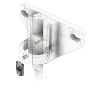
The attached shows a V block for my Nikon 6 Shadowgraph. I printed the t-nuts, M5 thread. Without chasing with a tap they are snug right out of the printer. Ditto with the clamp. T-nuts are 3.7mm tall so not your usual milling machine size.
Attachments
Last edited:
The more expensive versions of AlibreCAD do model the threads. Here following a tutorial I dropped 4.

Somewhat related conversation. I've downloaded McMaster-Carr CAD files for fasteners for assemblies into my parts library. Makes for very quick work just grabbing a bolt or nut or setscrew or whatever. Tree on left shows the steps involved in making a single SHCS including configurations for different fastener length, unthreaded length etc. I suspect Johns example is a dedicated subset of these same features, which is nice to have that capability.
For things like assemblies I similarly suppress the fastener threads unless they are specifically required for something. You can use these parts in a different way. Even if you didn't want to cut the thread from base principles, you could import something similar & utilize some of the dimensional features to 'subtract' material from the solid. I can see instances where that could save time & also the opposite.
Threads is CAD may not be slam dunk anyway, all machinists know that. Do you want 75% thread engagement or 50% based on material? That affects pilot hole & what remains of the thread in cross section. You could have an un-threaded (oversize drill) segment, or head counterbore, radial/depth counterbore offset distance, type/angle of counterbore, thread termination details .. on & on. So even the 1-click methods have limits depending on what is required. I think when it comes to CAM/CNC this really needs to be nailed down somehow. But for manual machining. you want the ability to fully define it in your drawing, either manually or automatically via the software.
gerritv
Gerrit
In Fusion360 there is a set of threads supplied. If you need further options, e.g. different fit classes then you can modify the thread parameters tables. Or add your own, eg. BA or Whitworth. https://www.autodesk.com/support/te...fdcarticles/Custom-Threads-in-Fusion-360.html
Looks like F360 has good capabilities that would suite most needs.
Another option, at least with parametric modelers, is design tables. Every parameter that uniquely defines a thread form (angle, depth, nose profile, helical pitch...) is a dimension. Therefore that dimension can also be a named variable, which in turn can be redefined with a different value in configuration tables so long as the geometry makes sense. SW reverts to Excel for design tables so you just copy rows & populate the cells. Cut, paste, delete, its really quite easy. I do that for fasteners, make one bolt, then design table configurations for the 20 available sizes or whatever.
Another option, at least with parametric modelers, is design tables. Every parameter that uniquely defines a thread form (angle, depth, nose profile, helical pitch...) is a dimension. Therefore that dimension can also be a named variable, which in turn can be redefined with a different value in configuration tables so long as the geometry makes sense. SW reverts to Excel for design tables so you just copy rows & populate the cells. Cut, paste, delete, its really quite easy. I do that for fasteners, make one bolt, then design table configurations for the 20 available sizes or whatever.
I turned that off too. Plus automatically orientating for sketches.This one would flip the model to what fusion thought was the best orientation. I would lose orientation. I turned that one off.
With my SpaceMouse, I just change to the orientation I want, I don’t need help From a program deciding what I need to look at.