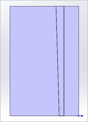
This happens because of the compound angle formed between the dovetail angle and the gib's taper angle. Even if the dovetail was square not at 120 included, rotation of a tapered object on a plane results in change of angles projected on a common view plane(if that makes any senseWhy did the angle change in your model photo?
") )
)
Last edited: