• Scam Alert. Members are reminded to NOT send money to buy anything. Don't buy things remote and have it shipped - go get it yourself, pay in person, and take your equipment with you. Scammers have burned people on this forum. Urgency, secrecy, excuses, selling for friend, newish members, FUD, are RED FLAGS. A video conference call is not adequate assurance. Face to face interactions are required. Please report suspicions to the forum admins. Stay Safe - anyone can get scammed.

Motion when locking the axis

Dabbler

ersatz engineer
But that's exactly the problem: the table on Y is almost sticky yet it's loose side to side i.e. not rigid enough.
Oh my. Theorizing may not be enough. On another member's table we had 'weird things' and it took 2 of us multiple trips and several hours to truly understand the thing.

I'm sorry you are so far away - I'd love to get my hands on the machine and perhaps understand things better. -- There could be dozens of reasonable theories, any one might be true. I think/hope that getting the new gibb, fitting it properly for height, and installing/adjusting it properly will simply solve the problem...
 

Susquatch

Ultra Member
Administrator
Moderator
Premium Member
@Eyecon - NEWSFLASH!!!

I was able to sneak out to my shop today to look at my various Gibbs.....

Two of them do exactly the same thing as yours does - perhaps even more. Yet they work perfectly in terms of resulting play.

The cause is clearly (clearly to my damn near blind eyes anyway) exactly what @PeterT describes. The direction of rotation of the screw lifts the Gibb exactly as he describes. If I insert a shim, the Gibb does not lift, but as stated above, it's position either lifted or stopped from being lifted, or stopped from dropping makes no difference at all in the measureable play of the table.

I suspect that your model is incorrect. None of my Gibbs have the ramp you described earlier. Except where the screw engages (where there is a ramp), my gibbs are both flat. In other words, the two Gibb surfaces are parallel, but tapered lengthwise. In this context, lifting or not lifting does not (and would not) affect their function.
 
Last edited:

Susquatch

Ultra Member
Administrator
Moderator
Premium Member
@Eyecon - given what I found in my previous post (#63 above), I put my mind to the question of what else might be causing your play. I think the Gibbs was a fun distraction.

Have you thoroughly cleaned them yet? If not, the table should be removed, the ways & dovetails on both halves, and both Gibbs thoroughly cleaned, then examined for filings, burrs, dirt, shipping grease, rust protectant, varnish, and other minor interference. Then lightly oiled with clean hands and reassembled for testing.

I'd highly recommend ignoring the Gibb movement for now. You may need to come back to it, but for now try to ignore it and put your mind to other possibilities.

I don't remember you saying exactly where you measured your play. Could you do a drawing for us (or even a photo) so we can see your indicator setup and the relative distances?

I'm also a little nervous about being overly sensitive to play on a new machine. It wouldn't take much breakin to significantly reduce the kind of play you measured if it was just a few slight imperfections. To that end, I might be tempted to just run the table back and forth to each extreme a couple of dozen times, then retighten, and retest to identify and compare any change.
 

PeterT

Ultra Member
Premium Member
My limited exposure to gibs is confined to my own machines & a few comparable others I've glanced at. They vary a bit in how the adjustment screw engages the gib end. Some have an extended tang, some have a notch, some have a partial counterbore, some look like they just press obliquely. Detecting axial movement should be easy, just put an indicator on the end of the strip & screw it in repeat from the other side. That should settle the issue of are they being displaced axially & to what amount. If an adjuster is bottoming out prematurely, gib has moved as far as it can go & table has noticeable movement, then its indicating the gib is short or something amiss with counterbore. You could possibly epoxy a sacrificial piece just to test the theory.

But I haven't seen any gibs that lift to the extent of the video. Maye that issue is being compounded by where the adjuster is on that particular mill vs some of these examples. But I cant help but thinking if there was a topside shim to take up the gap as @RobinHood sketch shows, that could also be tested. Just bond it on with 5 min epoxy. It will hold well enough for a test & will soften/debond with a heat gun. (Please do a small test section first just to be sure).
1681775722492.png 1681775815205.png 1681775942281.png
1681775982511.png
 

PeterT

Ultra Member
Premium Member
might be tempted to just run the table back and forth to each extreme a couple of dozen times, then retighten, and retest to identify and compare any change
That was another point, maybe its been dealt with already. Is the table behaving differently with leadscrew assembly in there (hand cranking)? Because if you have any kind of binding issues related to the leadscrew and set the gib on that basis, then move table to a different table position & its now looser, then I suspect the leadscrew is complicating/masking the gib fit. If LS was removed & all you focused on was the gib fit & slide, it should be repeatable down the whole travel (on a new machine with no wear). THEN if the LS makes it feel diferent, it could be related to LS alignment, ABL nut positioning etc.
 

Susquatch

Ultra Member
Administrator
Moderator
Premium Member
But I haven't seen any gibs that lift to the extent of the video.

Without a measurement of the lift all I can go by is the visual perception. To me, mine looks even worse. But yet the play is just fine!

With a Gibb with parallel faces, the lift should not make any difference to play. With a Gibb with non-parrallel faces (assuming there is such a thing), lift should be virtually impossible (no matter how much gap there is or is not) especially not with such a small amount of screw turning.

Consider how much that Gibb is lifted by the screw. It's practically a 1:1 ratio to the thread leade (fun to use that word here lol). Now consider how much the Gibb would have to move to get that lift.

I really doubt that the lift is related to the play. I have more or less discounted the issue in my mind. There is something else wrong.
 
Last edited:

Eyecon

Active Member
I suspect that your model is incorrect. None of my Gibbs have the ramp you described earlier. Except where the screw engages (where there is a ramp), my gibbs are both flat. In other words, the two Gibb surfaces are parallel, but tapered lengthwise. In this context, lifting or not lifting does not (and would not) affect their function.
I think I may have given the wrong impression: the gibs I have are only tapered in thickness but their two thin faces are parallel at least visually. Good to know that the lifting motion doesn’t necessarily contribute to incorrect gib placement and therefore doesn’t contribute to potential slop…at least in your case. Your other point about binding in the LS is very interesting, I didn’t check that methodically but all i can say is that loosening the gibs on both X and Y results in consistently smooth wheel movement I.e. I don’t feel any binding on the LS’s across the range of travel.

As for cleaning: that’s the very first thing I did…the machine was packed with excessive sticky way oil on all surfaces, before doing anything I cleaned all surfaces and way thoroughly using kerosene…I used white lint free rags and didn’t stop cleaning until the rags showed no signs of dirt. While I did not disassemble the table and saddle, I did take out the gibs to make sure there are no chips or grinding dirt anywhere, ofcourse for the other sides of the dovetails, I kept moving axis back and forth to clean behind the dovetails…again I didn’t stop cleaning until fresh rags were showing no to very little signs of dirt. I also soaked cotton twine in kerosene and ran it across the x and y screw to get rid of all the dirty grease and applied fresh synthetic grease to the nuts and the screw
 

Eyecon

Active Member
@Susquatch @PeterT @Dabbler, I’ll start from scratch and try to be more methodical in my testing. I’ll take pictures of my testing setup and make measurements of my X and Y gibs and report back….maybe I was too sloppy with my testing and was seeing things that weren’t really there or perhaps as stated, there a completely different issue at play here. Thank you all so much for taking the time to help me figure this out, I really appreciate it!
 

Susquatch

Ultra Member
Administrator
Moderator
Premium Member
I think I may have given the wrong impression: the gibs I have are only tapered in thickness but their two thin faces are parallel at least visually. Good to know that the lifting motion doesn’t necessarily contribute to incorrect gib placement and therefore doesn’t contribute to potential slop…at least in your case.

If your Gibb faces are parallel then I don't think it contributes in your case either. They would have to be horrible before it could. It's sorta like saying that offset 123 blocks have a different stack height than perfectly aligned ones.

Your other point about binding in the LS is very interesting, I didn’t check that methodically but all i can say is that loosening the gibs on both X and Y results in consistently smooth wheel movement I.e. I don’t feel any binding on the LS’s across the range of travel.

That was really @PeterT s point, but I do agree.

As for cleaning: that’s the very first thing I did…the machine was packed with excessive sticky way oil on all surfaces, before doing anything I cleaned all surfaces and way thoroughly using kerosene…I used white lint free rags and didn’t stop cleaning until the rags showed no signs of dirt. While I did not disassemble the table and saddle, I did take out the gibs to make sure there are no chips or grinding dirt anywhere, ofcourse for the other sides of the dovetails, I kept moving axis back and forth to clean behind the dovetails…again I didn’t stop cleaning until fresh rags were showing no to very little signs of dirt. I also soaked cotton twine in kerosene and ran it across the x and y screw to get rid of all the dirty grease and applied fresh synthetic grease to the nuts and the screw

Since you didn't take the table off, disassemble it, clean it, and carefully inspect it in there too, I'd say you have work to do! I'm not saying that's the issue, nor that this should be normal practice, but I am saying that I think it's a possible cause that you need to eliminate. Compared to other causes, this is both an easy step and a probable explanation.
 

Eyecon

Active Member
obliquely. Detecting axial movement should be easy, just put an indicator on the end of the strip & screw it in repeat from the other side. That should settle the issue of are they being displaced axially & to what amount. If an adjuster is bottoming out prematurely, gib has moved as far as it can go & table has noticeable movement, then its indicating the gib is short or something amiss with counterbore.
I can definitely confirm that the gibs are axially stable on both X and Y at least visually. On the problematic Y gib, I do see oil squeezing out when i try to lock the axis but not on X. I can also hear the side to side play on the Y axis when I rock the saddle only back and forth…I hear the ways and gibs stickness as they try to suck in a little air…hard to describe but you hear the play through the oil between the base and the saddle (Y ways) but not between the table and the saddle(X ways). I wish I could easily share videos on this forum to better explain what I’m seeing

In any case as mention, I will repeat all the tests keeping in mind all the advice I got from you and others on this thread and report back more methodically
 

Susquatch

Ultra Member
Administrator
Moderator
Premium Member
I can definitely confirm that the gibs are axially stable on both X and Y at least visually. On the problematic Y gib, I do see oil squeezing out when i try to lock the axis but not on X. I can also hear the side to side play on the Y axis when I rock the saddle only back and forth…I hear the ways and gibs stickness as they try to suck in a little air…hard to describe but you hear the play through the oil between the base and the saddle (Y ways) but not between the table and the saddle(X ways). I wish I could easily share videos on this forum to better explain what I’m seeing

In any case as mention, I will repeat all the tests keeping in mind all the advice I got from you and others on this thread and report back more methodically

Your description of air sucking is awesome! I can almost hear it from here!

Yup, sounds like a piece of dirt or metal in there.

Your call if you want to disassemble and clean inside first or do some detailed methodical measurements first. But I'd do the deep clean and close inspection first if it were mine.

Is your 728 the ultra precision version?
 

PeterT

Ultra Member
Premium Member
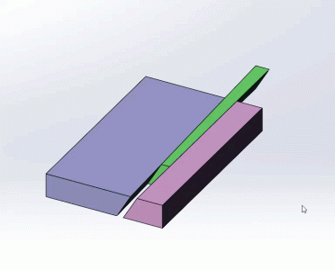
hmm.. this is tougher in cad than I thought. I have the conventional gib action working, exaggerated in video. But when I rotate the gib on one end, its kind of tricky to detect the difference between surfaces. I have the green gib mated to the blue block but of course I cant mate the pink block, the planes are no longer parallel. I may have to slice a scion & measure surface angles or something. I'm starting to doubt the the difference is a lot, OTOH we are talking thou's & these are just make belief surfaces to see if I could do it. I'll have to leave this for now.

1681784451627.png
 

Eyecon

Active Member
Your description of air sucking is awesome! I can almost hear it from here!

Yup, sounds like a piece of dirt or metal in there.

Your call if you want to disassemble and clean inside first or do some detailed methodical measurements first. But I'd do the deep clean and close inspection first if it were mine.

Is your 728 the ultra precision version?
Yes it is the ultra precision version, that's the only one they sell now at least as of a month ago when I bought it. That's exactly what I'll do, I'll take it apart and do a thorough cleaning and assembly everything carefully so I eliminate the variables.
 

Eyecon

Active Member
hmm.. this is tougher in cad than I thought. I have the conventional gib action working, exaggerated in video. But when I rotate the gib on one end, its kind of tricky to detect the difference between surfaces. I have the green gib mated to the blue block but of course I cant mate the pink block, the planes are no longer parallel. I may have to slice a scion & measure surface angles or something. I'm starting to doubt the the difference is a lot, OTOH we are talking thou's & these are just make belief surfaces to see if I could do it. I'll have to leave this for now.

View attachment 33692
This appears to be Solidworks so I'm not sure how joints work. But in Fusion 360, I mated all 3 components together and grounded only one of the dovetail components. The mating joints were of revolute type(allows rotation around the plane) but I could have also used planar(allows rotation + co-planar translation) between the 3 mating surfaces of the components. What I was looking for is what happens to the floating dovetail if the gib is rotated. This confirmed to me that assuming all dovetails are coplanar to the gib sides, any rotation in the gib causes the floating dovetail to go "out of square"(I was measuring angle of the vertical side of the floating dovetail to the ground plane in my case). Since this is impossible on the machine because both dovetails are effectively grounded(or at least not supposed to move out of plane), this led me to the conclusion that a rotating dovetail means the mating surfaces must not be coplanar in real life. This is probably obvious and of course doesn't tell us which surface is problematic, it was just a way for me to visually understand how the compound angles work. In reality also there is a possibility that the gib is actually bending not pivoting as shown in your picture, but I didn't go that far with my setup :). All this assumes there are no gaps between the mating surfaces though, any gap will allow for the gib to rotate without forcing the floating dovetail to go out of plane...again all theoretical.
 
Last edited:

Eyecon

Active Member
Until I reset and redo the measurements I thought I'd share the below video showing Keith Rucker fitting a tapered gib in a restored Monarch lathe:


I know Keith makes it look easy but this is the process I was thinking of following to refit the existing gib or for that matter the gib blank. Keep in mind that my existing gib is already scraped so I was just thinking that wedging the gib like Keith did in the video would eliminate the lifting effect of the screw and initially confirm if there are any issues with the mating surfaces. Also this way if the surfaces are matching but when installed the screw pivots the gib, we can possibly conclude that the issue is that the gib is not tall enough(maybe?)

Of course I won't attempt any of this now before cleaning and redoing all my measurements :)
 
Last edited:

Susquatch

Ultra Member
Administrator
Moderator
Premium Member
Yes it is the ultra precision version, that's the only one they sell now at least as of a month ago when I bought it. That's exactly what I'll do, I'll take it apart and do a thorough cleaning and assembly everything carefully so I eliminate the variables.

Don't forget careful inspection too! Ive always marvelled at how sensitive my big fingertips are! But my bride is simply amazing! Sometimes I think she can feel a tenth!
 

Eyecon

Active Member
Another simple trick to figure out if the gib fit is off or if something else is going on, would be easy to try since I'm taking apart everything for cleaning:

 
Top