• Scam Alert. Members are reminded to NOT send money to buy anything. Don't buy things remote and have it shipped - go get it yourself, pay in person, and take your equipment with you. Scammers have burned people on this forum. Urgency, secrecy, excuses, selling for friend, newish members, FUD, are RED FLAGS. A video conference call is not adequate assurance. Face to face interactions are required. Please report suspicions to the forum admins. Stay Safe - anyone can get scammed.

Motion when locking the axis

Why did the angle change in your model photo?
This happens because of the compound angle formed between the dovetail angle and the gib's taper angle. Even if the dovetail was square not at 120 included, rotation of a tapered object on a plane results in change of angles projected on a common view plane(if that makes any sense :))

1681910437612.png
1681910473441.png


1681910518974.png
 
Last edited:
This happens because of the compound angle formed between the dovetail angle and the gib's taper angle. Even if the dovetail was square not at 120 included, rotation of a tapered object on a plane results in change of angles projected on a common view plane

^Exactly^


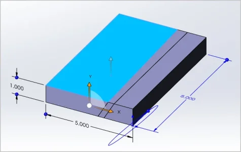
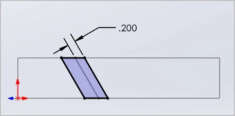
I'll figure out the dimensions used when I have a sec, but they were just arbitrary to get the workflow initialized. Not intending to model the subject mill. Maybe 10" long gib & dovetail blocks? But I also exaggerated the gib included angle to magnify results because I was already guessing net displacement would be teeny.

And probably useful to step back & consider other more probable real life factors as others have already suggested. For example are all 3 dovetail angles 60.0000 degrees on a Chinese mill? Probably not. What happens if block A is 59.5-deg and block B is 60.5-deg. Even with perfect 60-deg gib angles, strange mating would occur when the gib is inserted to the point of 'contact'. Its probably resting on a point, also likely now displaced in a roll orientation depending on which face it mostly meets. Maybe some slight bending for good measure. The mind boggles. Even a cad model would have real difficulty simulating this. But by bracketing a problem with more simplistic assumptions you can sometimes get a better feel. At least that's how I like to approach things.
 
Last edited:
This happens because of the compound angle formed between the dovetail angle and the gib's taper angle.

Only because your measurement reference is the face of each component in your model do you get a compound angle. If you take a section cut anywhere along the length inside the gib, the angle remains that of the original dovetail / gib / dovetail angle (120* in your model).

I believe @Susquatch was pointing that out also in and earlier post.

In real life, the angle between the two parts does not change. If it did, one part would have to physically twist - which it does not.

The three mating surfaces remain co-planar.

The gib just moves up (or down) within the two constraining dovetails. Yes, the distance between the two dovetails changes (if allowed to move) based on the amount the gib moves up or down.

In the Y-axis case, an upwards movement of the gib tries to increase the distance - but of course it can’t so it jams up the saddle.

If the gib could move down (it can’t because of the way it sits on), the distance would decrease if all surfaces remained in contact.

The above two conditions assume the pivot point of the gib is at the thin end bottom - which could be reasonable since the rear adjusting screw forces that side of the gib down onto the way.
 
I'll figure out the dimensions used when I have a sec, but they were just arbitrary to get the workflow initialized. Not intending to model the subject mill. Maybe 10" long gib & dovetail blocks? But I also exaggerated the gib included angle to magnify results because I was already guessing net displacement would be teeny.

There is no rush Peter. I'd just like to evaluate some of the numbers using old fashioned math to see what the range of reasonable numbers are. I used a slide rule back in my school days and an HP RPN calculator after that so I'm comfy doing the old fashioned math. I don't care if the numbers are only representative as long as they are the same ones that you used.

Are you comfy with @eyecons description of the angle change question I asked?

The above two conditions assume the pivot point of the gib is at the thin end bottom - which could be reasonable since the rear adjusting screw forces that side of the gib down onto the way.

I agree with everything you said except potentially this one. I could interpret this statement several ways. I don't think you meant that the gib rotates about the bottom rear edge. I think you meant that it rotates about an axis that is perpendicular to the parallel faces. Unless the Gibb lifts, that axis will also be through the rear bottom corner with the greatest included angle. Using your own logic, rotating about the length of the bottom edge would force it to warp as it rotates. But rotating about an axis that is 90 degrees to the faces, allows it to slide along them without warping. Of course, one can always force the gib to rotate around a different axis and bend the Gibb but that isn't what really happens. The Gibb follows the path of least resistance sliding up along the adjacent face.

@PeterT & @Eyecon - I am a bit gun shy about offending anyone. If you think I am pushing those boundaries please shoot me a PM and I'll simply drop out of the discussion. I really only want to help and if I'm not helping then I'll be happier if I just stay out of it.

Frankly, I think it's a fun discussion because it improves everyone's understanding of the physical geometry no matter which way they lean.
 
I think you meant that it rotates about an axis that is perpendicular to the parallel faces. Unless the Gibb lifts, that axis will also be through the rear bottom corner with the greatest included angle. Using your own logic, rotating about the length of the bottom edge would force it to warp as it rotates. But rotating about an axis that is 90 degrees to the faces, allows it to slide along them without warping. Of course, one can always force the gib to rotate around a different axis and bend the Gibb but that isn't what really happens. The Gibb follows the path of least resistance sliding up along the adjacent face.

Yes, you are exactly correct about the axis of rotation. Thanks for pointing that out.

I also agree that this discussion about geometry in the models (and me nitpicking) may not even be the problem and does nothing for @Eyecon to help solve the issues with the Y-axis gib.
 
@PeterT & @Eyecon - I am a bit gun shy about offending anyone. If you think I am pushing those boundaries please shoot me a PM and I'll simply drop out of the discussion. I really only want to help and if I'm not helping then I'll be happier if I just stay out of it.
Not at all! the different points of views are brining more clarity as how tapered gib geometry interacts with the dovetails in ways I wasn't thinking about before. I'm finding this discussion really useful and a lot of fun!

I also agree that this discussion about geometry in the models (and me nitpicking) may not even be the problem and does nothing for @Eyecon to help solve the issues with the Y-axis gib.
The discussion certainly helps me with a better understanding of the different possibilities of what could be wrong. I started with one set idea of what's wrong and I was completely convinced that the issue can only be wrong taper geometry. I now understand that that there are several possibilities behind what I'm observing on my mill. This is not only contributing to finding multiple solutions to the problem but possibly an improvement to how this mill is designed. For example even if the gib taper geometry and fit is the main problem, the fact that the gib is not tall enough is something that needs to be addressed in all cases either via the new gib blank or via shimming. This is something I didn't completely understand in the beginning of this discussion.

Again, I thank all of of you for your valuable contributions and ideas in trying to help me solve this problem!
 
Only because your measurement reference is the face of each component in your model do you get a compound angle. If you take a section cut anywhere along the length inside the gib, the angle remains that of the original dovetail / gib / dovetail angle (120* in your model).
I think the intent behind highlighting the angle change is that this angle change happens relative to the angles of the dovetails which are supposed to be coplanar. The angle of the sides of the gib doesn't actually change as you stated, it only changes relative to one of the two dovetails. So if it's making contact with the dovetail on the right, the gib's "dovetail angle" is changing relative to the other dovetail on the left(of course it can be the other way or can be floating and doing something in between). The angle change is not much but enough in my opinion to make the gib a little loose on one of its ends allowing the adjustment screw to push it up. It just very hard to tell what was happening on the other end that wasn't lifting: it was either rotating around a point towards the back(around a line parallel to the X axis) or simply bending in place...there was very little movement and I was using an inspection mirror to view the rear of the gib(the thinner end) so I couldn't really tell what was happening. Bottom line is it was not completely loose in there, it was pushed far enough to make the Y axis movement very sticky yet it was somehow loose enough for the adjustment screw to push it up. My conclusion so far is this could be generally due to a bad fit(wrong taper angle, surfaces are not flat, there is dirt in there...etc) OR simply that the gib was not tall enough to resist being skewed in place as it was.
 
@PeterT & @Eyecon - I am a bit gun shy about offending anyone. If you think I am pushing those boundaries please shoot me a PM and I'll simply drop out of the discussion. I really only want to help and if I'm not helping then I'll be happier if I just stay out of it.
No worries from my end. We went off on our usual tangent but I think everyone picked up a new perspective. Might not be entirely applicable or practical for the real world, but you never know. There's more to gibs & dovetails than meets the eye.

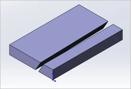
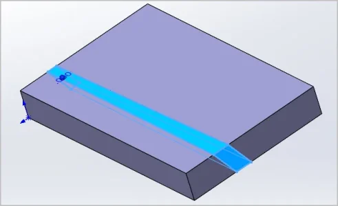
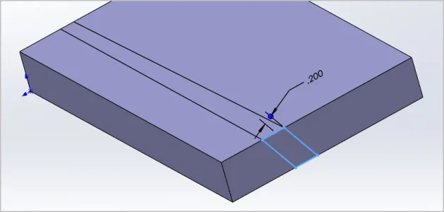
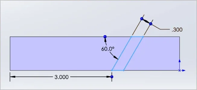
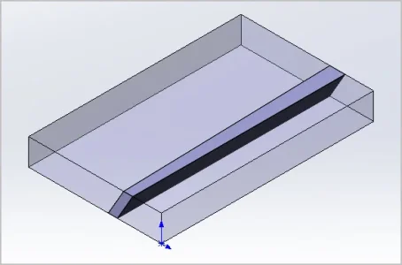
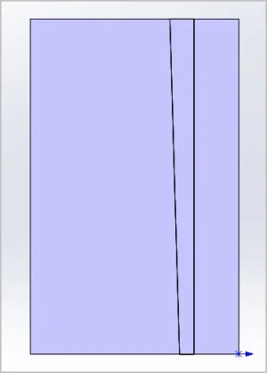
Sorry to bung up the post one more time with attachments but this is about the easiest way to show my defining dimensions. Again, completely arbitrary, not intending to simulate the mill. If there is another dimension you need me to pick off for convenience just ask. There's a couple different ways to go about this but I decided to slice a gib from a rectangular blank, save out the solid bodies & then bring them together in an assembly with defined mates & constraints. If Humpty Dumpty comes together again with same dimensions before moving things around, I feel confident of the parted components. I probably should have built a real mill table but this whole episode was really just a scratch pad that morphed. I'm kind of intrigued by non-60-deg dovetail angles now, but leave that for another day.
 

Attachments

  • SNAG-19-04-2023 11.23.26 PM.webp
    SNAG-19-04-2023 11.23.26 PM.webp
    11.2 KB · Views: 3
  • SNAG-19-04-2023 11.22.38 PM.webp
    SNAG-19-04-2023 11.22.38 PM.webp
    12.1 KB · Views: 2
  • SNAG-19-04-2023 11.22.10 PM.webp
    SNAG-19-04-2023 11.22.10 PM.webp
    15.7 KB · Views: 3
  • SNAG-19-04-2023 11.21.01 PM.webp
    SNAG-19-04-2023 11.21.01 PM.webp
    7 KB · Views: 4
  • SNAG-19-04-2023 11.20.21 PM.webp
    SNAG-19-04-2023 11.20.21 PM.webp
    19.2 KB · Views: 4
  • SNAG-19-04-2023 11.24.13 PM.webp
    SNAG-19-04-2023 11.24.13 PM.webp
    14.4 KB · Views: 3
  • SNAG-19-04-2023 11.42.24 PM.webp
    SNAG-19-04-2023 11.42.24 PM.webp
    4.3 KB · Views: 3
  • SNAG-19-04-2023 11.43.49 PM.webp
    SNAG-19-04-2023 11.43.49 PM.webp
    2.7 KB · Views: 3
Back
Top