Then how come I can't find the end of the packing tape?I have been told a journeyman toolmaker can feel 3 tenths, and a good toolmaker less than 2 tenths, just by feeling the surface of a clean, dry part.
How about this:

Then how come I can't find the end of the packing tape?I have been told a journeyman toolmaker can feel 3 tenths, and a good toolmaker less than 2 tenths, just by feeling the surface of a clean, dry part.
How about this:
Then how come I can't find the end of the packing tape?
Keep in mind that my existing gib is already scraped so I was just thinking that wedging the gib like Keith did in the video would eliminate the lifting effect of the screw and initially confirm if there are any issues with the mating surfaces. Also this way if the surfaces are matching but when installed the screw pivots the gib, we can possibly conclude that the issue is that the gib is not tall enough(maybe?)
Then how come I can't find the end of the packing tape?

The CAD models are only meant to show that vertical movement of the gib on one end but not the other(like in my case) means that the gib is not making full contact on the dovetails on both sides (i.e. the mating surfaces are not coplanar). I think your statement is absolutely correct though(at least if I understood what you were saying): vertical movement of the gib on both ends is totally inconsequential, but any pivoting movement (the front lifts, the back drops for example) means that the 3 surfaces have an uneven gap between them (in my case possibly big gap between the dovetails and the gib in the front, but no gap in the back allowing the front screw to life the gib). Why does this matter? based on my understanding from the model, this uneven gap means that the saddle or table or whatever the gib is supposed to help slide can be wedged stuck not allowing for the surfaces to slide yet the setup can still wiggle side to side(this of course is the extreme case).The only way for that to happen is with a Gibb that moves longitudinally. I don't think the Vertical movement at the screw translates into longitudinal movement.
")
The CAD models are only meant to show that vertical movement of the gib on one end but not the other(like in my case) means that the gib is not making full contact on the dovetails on both sides (i.e. the mating surfaces are not coplanar). I think your statement is absolutely correct though(at least if I understood what you were saying): vertical movement of the gib on both ends is totally inconsequential,
This is no different than what you already suggested as well, if there is dirt or a chip stuck between the gib and dovetail, the gib can be pushed in very tight against the dove tails but because of that chip, some part of the gib will not be making full contact with the dovetails allowing the adjusting screw to move it up or down(this up and down movement can be pivoting around that high spot caused by the chip or simply bending the gib like a flexible steel rule).
All of this is possible because the gib is not tall enough to be constrained up and down by the saddle and the ways. if it was constrained this way, it wouldn't move up or down even if it's not making perfect contact with the dovetails.
well I think that's exactly where the problem is, if the gib/dovtails were not tapered or the dove tails were just square ways this would be true. The compound angles formed by the front to back taper in combination with the dovetail angle makes this impossible as the CAD model shows.Now consider four wedged parallels (tapered end to end in opposites). Again, the middle ones can be put in any position without affecting the others.
Its clearly more than 3/10s so of course you can't find it silly boy.....Then how come I can't find the end of the packing tape?
I think you may be in to something here. My gibs can also lift but I have none of the issues.The CAD models are only meant to show that vertical movement of the gib on one end but not the other(like in my case) means that the gib is not making full contact on the dovetails on both sides (i.e. the mating surfaces are not coplanar). I think your statement is absolutely correct though(at least if I understood what you were saying): vertical movement of the gib on both ends is totally inconsequential, but any pivoting movement (the front lifts, the back drops for example) means that the 3 surfaces have an uneven gap between them (in my case possibly big gap between the dovetails and the gib in the front, but no gap in the back allowing the front screw to life the gib). Why does this matter? based on my understanding from the model, this uneven gap means that the saddle or table or whatever the gib is supposed to help slide can be wedged stuck not allowing for the surfaces to slide yet the setup can still wiggle side to side(this of course is the extreme case).
I think Stefan Gottswinter's technique shows it it best. In his video, he is checking for gib fit by checking this side to side wiggle/slop, the gib is wedged in a little and one end has no slop while the other does..meaning that if you screw the gib in you can bind the dovetails completely but can still move them side to side(at least on one end). This is very similar to what I observed: I have the gib in far enough to make the axial movement sticky yet I was still measuring side to side slop perpendicular to the direction of movement.
This is no different than what you already suggested as well, if there is dirt or a chip stuck between the gib and dovetail, the gib can be pushed in very tight against the dove tails but because of that chip, some part of the gib will not be making full contact with the dovetails allowing the adjusting screw to move it up or down and also causing side to side slop despite the gib being pushed far in(this up and down movement can be pivoting around that high spot caused by the chip or simply bending the gib like a flexible steel rule).
All of this is possible because the gib is not tall enough to be constrained up and down by the saddle and the ways. if it was constrained this way, it wouldn't move up or down even if it's not making perfect contact with the dovetails.
I hope I'm making sense
This can be a more complicated combined motion, but just for this example, I left the axial position of the gib the same, rotate gib about lower edge of small end & constrain the mate between dovetail surfaces so they can slide. The bottom gib surface is inclined 2-deg for reference.
@PeterT awesome illustration! so not only is the front of the gib .0014" wider than the back, it would also be only making contact on the top edge of the opposing dovetail, all this can introduce side to side slop in the mechanism! And that's with the assumption that the surface are flat and matching in angle!
I'm not quite sure if this sequence will show the resultant dimensional differences properly but here goes. Remember my example is just made up dimensions, not the physical assembly
This shows the simplified table/gib model like my little movie. Blue stationary center section. Green gib mated to dovetail surface. Both are 60-deg angles. I omit the opposing table to the right of gib because I'm just looking for resultant dimensions on the thick end, Plane1
View attachment 33699
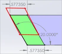
This shows the base case reference dimensions on the thick end. Top & bottom dimensions. The gib included angle is 60-deg so we get 120.000 deg angle between horizontal & gib surface. All as we would expect.
View attachment 33700View attachment 33704
Now we cock the gib strip up. This can be a more complicated combined motion, but just for this example, I left the axial position of the gib the same, rotate gib about lower edge of small end & constrain the mate between dovetail surfaces so they can slide. The bottom gib surface is inclined 2-deg for reference.
View attachment 33701View attachment 33705
Now take new measurements relative to same plane. The gib has now pushed out to 0.578709 at the top of blue surface, so subtract original 0.577350 = 0.0014" difference
Note the angle of the outboard gib surface is now greater than 120.0 deg vs horizontal so it cannot match the opposing casting dovetail plane. It would be a point contact with a wedge gap.
View attachment 33702View attachment 33703
If the gib moves up the side of the dove tail (blue surface) and the gib is a true parallelogram (in cross section) at any give point along its length, then the 120* angle would remain at 120* no matter how high the gib end is lifted off the reference surface.
You don't lift the Gibb about the lower edge of of the small end. You lift it about an axis that is 90 degrees to the long axis of the cross section.
You are free to postulate whatever constraints you prefer, evaluate them accordingly & ignore any others. You saw his video where the gib cocked up within the gap headroom when he turned the adjuster screw right? Did you see the opposite end move up the exact same amount simultaneously at the exact same time? No, neither did I. The absence of seeing something occur doesn't mean it did not occur or could not occur. Is just convenient spot to fill in your own theory.