@Eyecon the
@RobinHood sketch is exactly what I was driving at with my questions. I don't quite understand your CAD diagram & it might be leading you to a false conclusion, especially with the 90-deg simplification vs. what should be a parallelogram. An unresolved issue is that you have a large gap between the top of gib & the underside of slide. ie. they are different heights & therefore allowing degrees of freedom that should be very minimal IMO. We also still don't know if the gib height is the same height on both ends, you didn't answer my question so it makes it hard to fully understand the situation.
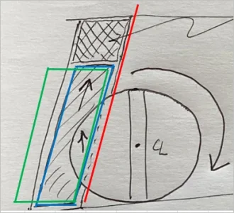
using this sketch green is the big end & blue is the small end. Typically they would be the same height but should extend to where he has the shim pack. If the gib is adjusted axially in & out of the paper, that translates into displacement in the X-direction (blue arrow) tightening or loosening, exactly what we want
View attachment 33655
what looks to be going on is the gib is displacing along the dovetail axis (red line) as a function of the adjusting screw rotation. Now it gets interesting. I think theoretically if both big & small gib ends (green & blue) rose exactly together there should be no net displacement in X. But if one end acts as kind of a pivot point staying low & the other end is being displaced up via the rotation direction of adjuster screws (further complicated by the adjuster actually pushing on the gib), then I suspect you will have some have some kind of compound displacement where its sticking in one area & not in another. Detecting this with blue rubbing off is meaningless because this displacement mode is not accomplishing the goal of adjusting the gib in the intended way as above. You have just landed at some in-between point where it feels about right, but its a false fit. Maybe I'm off base but this is how I perceive it with facts so far. Adding shims as a test to see if this eliminates the issue is exactly what I would recommend. Who knows, maybe your new gib will be the same height & the issue is how much relief they milled in the dovetails? Start with the easy stuff first.
View attachment 33654
")