• Scam Alert. Members are reminded to NOT send money to buy anything. Don't buy things remote and have it shipped - go get it yourself, pay in person, and take your equipment with you. Scammers have burned people on this forum. Urgency, secrecy, excuses, selling for friend, newish members, FUD, are RED FLAGS. A video conference call is not adequate assurance. Face to face interactions are required. Please report suspicions to the forum admins. Stay Safe - anyone can get scammed.

METAL LATHE SMOKE, RPM LOSS, NEW LATHE MOTOR?

@MooseMeat - I found that old thread for you.

Thread 'VFD Output Filtering' https://canadianhobbymetalworkers.com/threads/vfd-output-filtering.5996/

Pay special attention to @jcdammeyer's comments about coil saturation. This is the kind of thing that makes watching Clough42 and your VFD Filtering website so shallow. Both forget that it only works at low power levels. As soon as you crank up the load the coils saturate and might as well not be there. A classic example of "it worked great on the bench......"

As I have already stated. I gave up on trying to filter the output. It was waaaay too expensive to do that properly. It was easier to accept the noise and simply shield it from reaching anything else. That's how I arrived at using top notch shielded cable instead.

I probably have enough left for you too. But I don't know how to get it to you during the strike.
I really do appreciate the information, there can be so much information and information overload.

cheers..
 
@MooseMeat - I found that old thread for you.

Thread 'VFD Output Filtering' https://canadianhobbymetalworkers.com/threads/vfd-output-filtering.5996/

Pay special attention to @jcdammeyer's comments about coil saturation. This is the kind of thing that makes watching Clough42 and your VFD Filtering website so shallow. Both forget that it only works at low power levels. As soon as you crank up the load the coils saturate and might as well not be there. A classic example of "it worked great on the bench......"

As I have already stated. I gave up on trying to filter the output. It was waaaay too expensive to do that properly. It was easier to accept the noise and simply shield it from reaching anything else. That's how I arrived at using top notch shielded cable instead.

I probably have enough left for you too. But I don't know how to get it to you during the strike.
I had totally forgotten about that thread. My ELS has never been bothered by the VFD (Single Phase 220VAC to 3 Phase 220VAC) but that's because with 1 PPR and a minimum slot size each index pulses has to be about 200 uS long. Noise spikes are much narrower so they never interfere.

For systems that work with pulses that are edge triggered rather than width measured the noise issues can be unsettling.
 
i'm late replying to this one, but a VFD works by using high frequency pulses that create a pattern that emulates a sine wave of the desired period / frequency. That's why their output leads produce a lot of RF interference and shielding is helpful. Filtering the output leads impairs the ability for the motor to receive the correct wave form from the VFD, and for the VFD to analyze the back EMF from the motor

Filtering the input doesn't help the VFD per se, but it helps filter interference from propagating from the VFD back into the panel and onto other circuits.

your typical computer uses a rectifying power supply. that is a device that is inherently immune to the kind of harmonic interference that could come back from a VFD. It also produces its own interference of the same kind

despite the numerous warnings to the contrary, most neutral is actually ground. don't cross those wires unless you absolutely know what you are doing, because neutral wires are expected to carry current and ground ones are supposed to be a safety feature, but understand that at some point in your supply, they will be one and the same
 
i'm late replying to this one, but a VFD works by using high frequency pulses that create a pattern that emulates a sine wave of the desired period / frequency. That's why their output leads produce a lot of RF interference and shielding is helpful. Filtering the output leads impairs the ability for the motor to receive the correct wave form from the VFD, and for the VFD to analyze the back EMF from the motor

Filtering the input doesn't help the VFD per se, but it helps filter interference from propagating from the VFD back into the panel and onto other circuits.

your typical computer uses a rectifying power supply. that is a device that is inherently immune to the kind of harmonic interference that could come back from a VFD. It also produces its own interference of the same kind

despite the numerous warnings to the contrary, most neutral is actually ground. don't cross those wires unless you absolutely know what you are doing, because neutral wires are expected to carry current and ground ones are supposed to be a safety feature, but understand that at some point in your supply, they will be one and the same
hey,
So I have in hand now some shielded 12g cable and will replace the motor cable tomorrow and see what happens, both ends of the shielding gets grounded correct?? vfd side and motor side?
 
hey,
So I have in hand now some shielded 12g cable and will replace the motor cable tomorrow and see what happens, both ends of the shielding gets grounded correct?? vfd side and motor side?

No. Just one side. Typically the VFD side. The ground can go to both, but the shield should only go to the ground nearest the motor contacts on the VFD.

Glad you found some shielded cable.
 
I'm late replying to this one, but a VFD works by using high frequency pulses that create a pattern that emulates a sine wave of the desired period / frequency. That's why their output leads produce a lot of RF interference and shielding is helpful. Filtering the output leads impairs the ability for the motor to receive the correct wave form from the VFD, and for the VFD to analyze the back EMF from the motor

Filtering the input doesn't help the VFD per se, but it helps filter interference from propagating from the VFD back into the panel and onto other circuits.

your typical computer uses a rectifying power supply. that is a device that is inherently immune to the kind of harmonic interference that could come back from a VFD. It also produces its own interference of the same kind

despite the numerous warnings to the contrary, most neutral is actually ground. don't cross those wires unless you absolutely know what you are doing, because neutral wires are expected to carry current and ground ones are supposed to be a safety feature, but understand that at some point in your supply, they will be one and the same
Hi Mbond,

I 100% agree with you.
 
I'm curious:

1) Is the tach return power connection (black wire) still powered from Earth ground?
2) Did you try separating the power wiring leading to the tach from the tack signal?

In the previous picture the tach and power wiring were bundled together.
 
Last edited:
I'm curious:

1) Is the tach return power connection (black wire) still powered from Earth ground?
2) Did you try separating the power wiring leading to the tach from the tack signal?

In the previous picture the tach and power wiring were bundled together.

These are questions I asked (or suggested changing) earlier too.

The trouble is that we only know what we know, we don't know exactly how that translates to his install.

Curiosity is an understatement. I would LOVE to get my hands on @MooseMeat's install with an oscilloscope.
 
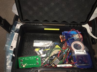
An oscilloscope might help, however in a electrical noisy environment a scope can be misleading. A Spectrum Analyzer is the tool of choice on my bench. I also have a pair of battery powered handheld EMC near field probes in my travel EMC kit that are made by Credance Technology that are really helpful for this type of situation.
_IMG_0032.jpg
 
A Spectrum Analyzer is the tool of choice on my bench. I also have a pair of battery powered handheld EMC probes in my travel EMC kit that are made by Credance Technology that are really helpful for this type of situation.

Ya, I always wanted a spectrum analyser. It was great when I could use the one from work. As an old retired yetti, it's not in the cards.

Insert huge pout here......

Tell us more about your EMC Probes...... I've never used anything like that.
 
Ya, I always wanted a spectrum analyser. It was great when I could use the one from work. As an old retired yetti, it's not in the cards.

Insert huge pout here......

Tell us more about your EMC Probes...... I've never used anything like that.


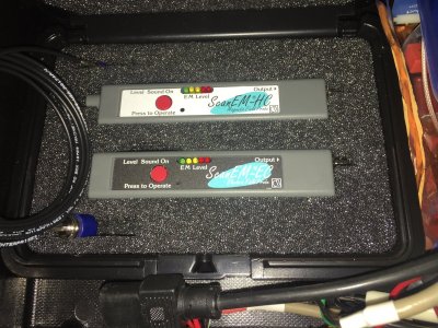
Here they are. When used in stand-alone mode, they have a little sensitivity adjustment and they output an audible tone proportional to the noise they receive. So you can hunt around a noisy device and the connected wiring and get a sense of where the noise is.

I also have a bunch of other EMC probes for the SA. Not a gazillion people out there with experience in EMI mitigation.
IMG_0033.JPG
 
I also have a bunch of other EMC probes for the SA. Not a gazillion people out there with experience in EMI mitigation.

Very true. Not just mitigation but also shielding and desensitizing. Where I worked we had an entire team of EMI Specialists. Vehicles produce a lot of EMI themselves. They are also regulated. That's the easy part. The hard part is making sure they don't stall and die under power lines, next to a welding shop, around electric motors and drive systems, and next to big relay banks, to pick just a few sources.
 
These are questions I asked (or suggested changing) earlier too.

The trouble is that we only know what we know, we don't know exactly how that translates to his install.

Curiosity is an understatement. I would LOVE to get my hands on @MooseMeat's install with an oscilloscope.
You will be pleased to know; ESPECIALLY Susquatch....😉 "I don't give a crap what the internet says" 😉

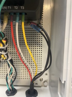
I just Installed the shielded cable and the tach issues went away, their is two ways to solve this problem and I would much rather use the proper shielded cable even given the cost @ 5ft for 60$. The braided shielding is wrapped in heat shrink and a terminal end, pretty delicate stuff to get the proper depth of cut to remove the outer shielding and keep the braid intact but it all worked out.

ps, I am making the wife a ferrite anniversary ring, came in a 20 pack so should be good till I really find out what happens in the very end.
 

Attachments

  • IMG_6897.JPG
    IMG_6897.JPG
    1.6 MB · Views: 1
I just Installed the shielded cable and the tach issues went away, their is two ways to solve this problem and I would much rather use the proper shielded cable even given the cost @ 5ft for 60$.

Not only that, but..... I'd wager pretty good money that your tach issues would come back when you load up a cutter with more current flowing through those ferrite cores, whereas the shielded cable will actually get better as the power goes up.

Make sure you move the power cables to another part of the cabinet as @slow-poke suggested. No point waving red flags at the EMR bully.
 
This is my bible when it comes to all things that might create electrical interference. I sure didn't pay $198 for it back when I bought it in 2009.

It's all I can do to put my socks on in the morning, between the engineers black book and feeding the cats I'm a wreck and that's before noon.

However, when I come across a problem I like to know how to fix it, or at least understand it, jack of all trade master of none; the advice and support here is A1+, even know Susquach doesn't give a crap about the inter web, that is going to stick with me and I plan on getting some mileage out that one.

Fellas, thank you all, I am looking forward to F-ing something else up just to get advise and instruction here.

A1 bunch of MOB's here, figure that one out.....😉
 
the advice and support here is A1+, even know Susquach doesn't give a crap about the inter web, that is going to stick with me and I plan on getting some mileage out that one.

That's already twice you did that. But it's ok. Fire away. Cuz it's true.

Anybody and their mother can put anything on the internet. If they post it, people find it in searches, read it, and believe it. Thats not good. Since I doubt we will ever establish realistic usable viable internet credibility ratings, I use my own. What is their expertise? How often are they correct? Do they have a reputation? Do others respect their opinions and advice? Do they have job related experience? Are they self anointed? Does what they say tingle my Spidey senses? What is the context of their advice?

Generally speaking, advice from people who do similar activities for a living is more credible than others. Support information on company websites is "usually" pretty good.

I don't generally find that information found on a forum is credible unless the forum member giving that advice is credible on their own merits.

I think Canadian Hobby Metal Workers has attracted a disproportionate number of highly credible members. I don't know why. But it is a source of great pride for me. I think the members here are amazing.


A1 bunch of MOB's here, figurethat one out.....😉

The original definition appears to be totally appropriate. Who needs acronyms! A mob is a large group of unruly disorganized and totally obstreporous people.
 
Lathe Mill related

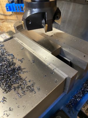
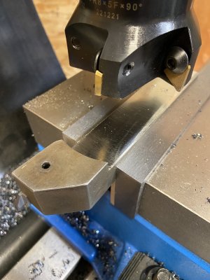
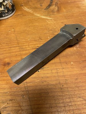
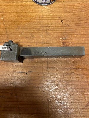
Well now the lathe is all back together, I have an abundance of tools from the purchase of the lathe and some of the carbide holders are way too big for the lathe so my first ever mill job was to cut these carbide holders down to size as to fit the tool post.

I made an attempt to tram the mill ( craftex knee mill) and turns out it was very good right outa the box so to speak but none the less I monky'd with it to see what was really going on an get it that much better.

here are a few pics of the first mill job,
 

Attachments

  • IMG_6901.JPG
    IMG_6901.JPG
    2 MB · Views: 7
  • IMG_6902.JPG
    IMG_6902.JPG
    1.8 MB · Views: 6
  • IMG_6903.JPG
    IMG_6903.JPG
    2.2 MB · Views: 7
  • IMG_6904.JPG
    IMG_6904.JPG
    2.5 MB · Views: 7
Hi David, Guys,

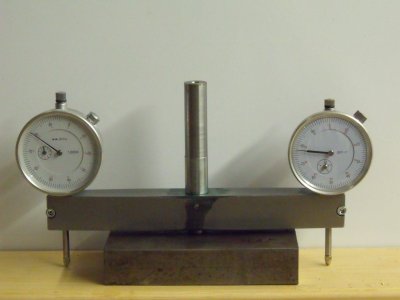
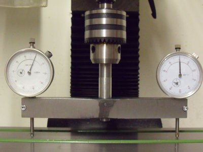
I made a dual meter device to set the tram on my mill. (Optimum BF20L) About the best modification that I have done to the mill is the three hole conversion. I can now set the head dead vertical with respect to the table and then lock it in place easily. Before I did this just tightening the two clamp screws would cause the head to move and nod slightly. A pair of fingers at the top of the head prevents any further possible movement.

dscf0010.jpgdscf0015.jpgDSCF0566.JPG

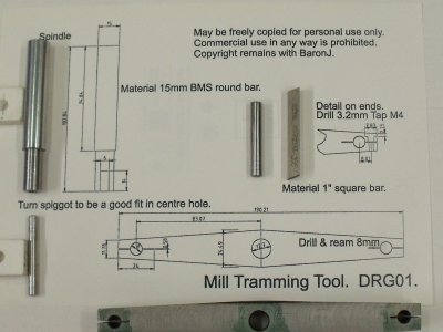
This is the drawing for tool made from a length of 14 mm thick steel 25 mm wide.
Actually a cleaned up slice from the end of a piece of 15 mm plate.
 
here are a few pics of the first mill job,

I prolly would not have used a face mill, but it's not a fussy job. If it works, it works!

Good thinking to remove the metal from the bottom of the tool. My first time, I removed it from the top. That was a mistake.

What is your tool post size? They do make tall tool holders for AXA, BXA, and CXA. this basically increases your tool holders to the next size up. Mine being BXA, takes 5/8" tools. The tall BXA holders take 3/4" tools.

I made a dual meter device to set the tram on my mill.

I'll readily confess that I don't think an indicator setup (either 1, 2, or 3) is nearly as useful as a tramming plate. A good plate makes the whole tramming process trivial.

I made a tramming fixture from a 12" OD brake disk. Brake discs are made to very exacting tolerances in order to prevent brake pedal throb and pulsing. A brake disc mounted ABOVE THE VISE, provides the following advantages:

1. You don't have to remove the vise to check or adjust tram.

2. You don't have to deal with T-slot incontinuities. You can just sweep smoothly and continuously.

3. But most importantly of all, a round disk provides a sweep range of 360 degrees extending the travel not just to both sides, but also behind and in front of the table making nod adjustments easy.

All you need is an inexpensive brake disk and 3 precision blocks - 2-4-6 blocks work great. You can buy them or make your own if you have a surface grinder (that's what I did). You can also make them on a mill but only if it's already trammed!

The blocks are placed on the table with two on one side of the vise front and back, and one in the middle on the other side. This allows the disk to be mounted above the vise.

Now you have a perfect surface that is perfectly parallel to your table on which to tram the mill head. Lots of members use two indicators and I made a fixture for 3 so I can tram without sweeping. But you can sweep if you want. One indicator is easy with the tramming plate. Two is easier, and 3 is easiest of all.

Here is a great thread from the past with lots of math, drawings, and ideas!

Thread 'Spindle square' https://canadianhobbymetalworkers.com/threads/spindle-square.4225/

Btw, @BaronJ - I don't recinme

 
Back
Top