• Spring 2024 meetup in Calgary - date Saturday, April 20/2024. discussion Please RSVP Here to confirm and get your invitation and the location details. RSVP NOW so organizers can plan to get sufficient food etc. It's Tomorrow Saturday! you can still RSVP until I stop checking my phone tomorrow More info and agenda
  • We are having email/registration problems again. Diagnosis is underway. New users sorry if you are having trouble getting registered. We are exploring different options to get registered. Contact the forum via another member or on facebook if you're stuck. Update -> we think it is fixed. Let us know if not.
  • Spring meet up in Ontario, April 6/2024. NEW LOCATION See Post #31 Discussion AND THE NEW LOCATION

King 1440 and Craftex Threading

DPittman

Ultra Member
Premium Member
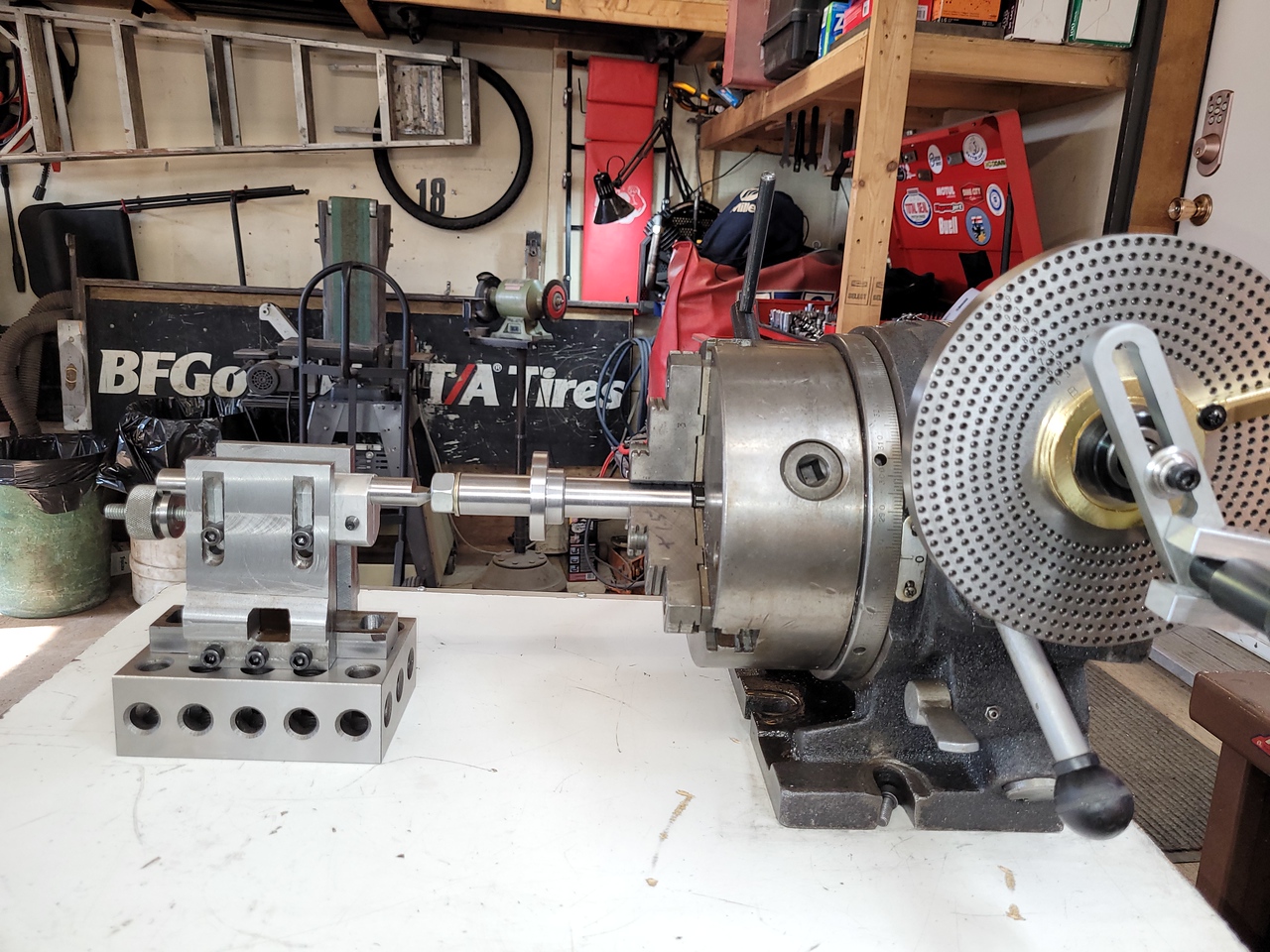
Looks like you're all ready to go! After successfully cutting those gears, you'll be looking for more to do.

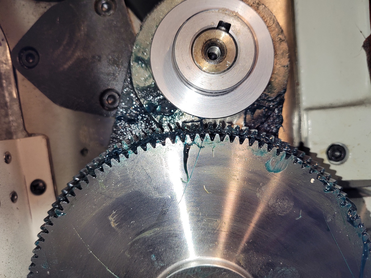
I've got a small idler lathe gear on my reverse tumbler that needs to be replaced. It has internal snap ring grooves to hold it in place which I'm not crazy about cutting and makes mounting the blank a bit different than what I've done in the past.

Keep us posted on your gears as some of us may forget:oops:
 

John Conroy

member
Premium Member
@John Conroy Is this new gear do that you can thread a specific size not currently available? Only reason I ask is I had some similar thoughts to achieve certain sizes, but quickly ran into the issue that the tooth count (pitch diameters) dictate the gear centers. So if the input/output shafts are fixed & is a dimensional mismatch, it requires something like the adjustment sector arm / idler gear, sub-assembly, not unlike my current / your old lathe. I'm sure you know all this but just in case. So far I'm batting 4 brain farts over 4 days, I just hope its not spreading LOL

Peter, you made me nervous that the 42 tooth gear was going to be too big to fit on the headstock/top shaft so I pulled the gear train apart and did a test fit. It fits with a couple millimeters to spare! I would have been pretty upset with myself if I cut all the teeth and the gear wouldn't fit.


My set-up with the super pacer and footstock will look like this. I'll set it up on the mill the verify clearance for the cutter but it looks like there will be room.


Bandit

Super User
This has been an interesting thread. Wanted to cut some 20 pitch threads on my 1340 Advance lathe that I had not used for threading before, were not 20, found they were 22 pitch. Some head banging, recheck all levers, all as should be according to the charts on lathe. Checked the drive gear train, all as should be. Started trying different pitchs, all tried were not at charted settings. This lathe has 2 shift levers and a 9 position dial, also left/right lever and a threading or power feed lever. Started playing with the 9 position dial,found it it would move about 1 position beyond the 1 or the 9 position. Strange, seemed to be some slack also, with mushy engagement at ether end.
Had seen blue silicone on cover plate instead of a gasket. This was a used lathe, brought by my father about 20 years ago. In for a penny, desided to remove cover. Gear oil in the box, wife not happy about the smell! So the dial turns a pinion gear which moves a rack which has a shift fork on it. Found that the fork mounting screws were loose. Tightened them, still did not move into right position. After watching movement of rack, found pinion was timed to rack wrong. Reset, looks good, moves and stops at each end on position marks.
Putting back together, the shift fork engages a peg on the gear slider but the piece pivots around the main gear cluster and drops down into the case 90 degrees from where it should be. A light weight string looped over it and tied up over the gasket surface. Put RTV grey on gasket surface, and eased cover into place, made sure fork was engaged with peg, pulled out string and replaced fasteners, lightly tighten, try all positions ,turning by hand.
A long story, but now works right.
 

Susquatch

Ultra Member
Administrator
Moderator
Premium Member
So here’s a question what are the common shaft sizes of the 100/127 gears?

I have no idea what the common sizes are, but I'll take mine off later today and measure it for you.

Silly question, why do you want to know that?
 

Susquatch

Ultra Member
Administrator
Moderator
Premium Member
So here’s a question what are the common shaft sizes of the 100/127 gears?

OK, I measured mine. The ID is 55mm. However, it is not a simple gear like the other two. My 127/120 has a bearing in it. The bearing is in a sleeve that is keyed to both gears, and the bearing and sleeve is retained by a snap ring.

20230401_110845.jpg

My regular gears have a 19mm bore and they are keyed to input and output shafts that have internal bearings in the gear box of the lathe.

20230401_111229.jpg

Edit - here is the big picture. The 120/127 is mounted on an adjustable Banjo.

The top gear a) turns 1:1 with the spindle and in the same direction. The 120/127 is a simple idler transferring the input from a) to the output b).

The output gear b) is the input to the quick change gear box which is a separate gear box from the spindle speed gear box. You can plainly see the separation between the two gear boxes in the photo.

20230401_111740.jpg
 
Last edited:

PeterT

Ultra Member
Premium Member
I'll have to snap a pic next time, but meanwhile here is pic from user guide of my (King) CT-1440-G alongside @Susquatch pic for comparison
 

Attachments

  • SNAG-2023-04-01 10.08.36 AM.jpg
    SNAG-2023-04-01 10.08.36 AM.jpg
    114.7 KB · Views: 9

Susquatch

Ultra Member
Administrator
Moderator
Premium Member
I like the shield to stop grease/oil getting on the belts, think I will try to add one on the 1340 though my setup appears closer to Susquatch's layout.

I think a shield is a good idea.

But it's never been a problem for me. I don't use a lot of grease though. Really only just enough to be able to say there is some there.
 

Proxule

Ultra Member
I skimmed through this thread more or less. Any easy way to figure out what TPI or feeds the norton gearbox can do, That are not listed?

Thanks
 

Susquatch

Ultra Member
Administrator
Moderator
Premium Member
I skimmed through this thread more or less. Any easy way to figure out what TPI or feeds the norton gearbox can do, That are not listed?

Thanks

The normal arrangement cuts each number in half so start at the top of each column and fill in the empty ones. If a top one is missing, then start at the bottom and double going up.

For whole columns that are missing, you can use the feedrates to determine the threading ratio difference.

Edit - if you send me a copy of your charts, I'll figure them out and then fill them out for you or show you how to do it yourself.
 

Bandit

Super User
My 1340 lathe appears to be the very same on the drive end as Susquatch's 1440? However it uses a 30 tooth on "a" shaft and a 60 on the "b" shaft. Have the 120/127 ideler setup the same also. 36 pitchs on hand, 8 to 112. Metric threading, with extra gear set of 4 gears, 28,35,36,50 tooth, plus the 30 and 60 already in the train.
Maybe interesting to put the a 60 tooth on "a" shaft with a 60 on the "b" shaft, will double " b" shaft speed.
But so far have never needed more than 40 pitch max on anything. I don't work on watches, LOL. I know, pictures-would be nice, way over my pay grade at this time.
Anyone that uses more then one finger to type is cheating.
 
Top