
-
Scam Alert. Members are reminded to NOT send money to buy anything. Don't buy things remote and have it shipped - go get it yourself, pay in person, and take your equipment with you. Scammers have burned people on this forum. Urgency, secrecy, excuses, selling for friend, newish members, FUD, are RED FLAGS. A video conference call is not adequate assurance. Face to face interactions are required. Please report suspicions to the forum admins. Stay Safe - anyone can get scammed.
You are using an out of date browser. It may not display this or other websites correctly.
You should upgrade or use an alternative browser.
You should upgrade or use an alternative browser.
JCDammeyer's 42 projects
- Thread starter jcdammeyer
- Start date


KootzDragon
no problems... just challenges
I also follow her...that car is on another level of clearly insane OCD quality....and without any sponsorsI follow a Youtube channel called Sarahntuned.
She is almost done putting a 2UZ V8 from her dad's crashed Tundra into a 74 Celica.
Took years.
My eyeballs started leaking when she revealed what the cars final destination is
The exhaust...gods I love that exhaust
KootzDragon
no problems... just challenges
Have you heard of a YouTube channel in the UK swapping a Conaught 2.0L V10 into a Miata...that is gonna neat if they ever get past planning it out....guess there's been some hurdles getting internals made ...I saw an early RX-7, with a 340 Dodge engine swap (did not quite fit under the hood)
They are light 2100-2300 lbs.
Say goodbye to the 50-50 weight distribution and handling, but say hello to some snappy acceleration.
I really liked my RX-7!

Well the paint is finally hard enough (no longer tacky) so I can handle the rest of the parts. Now all installed.
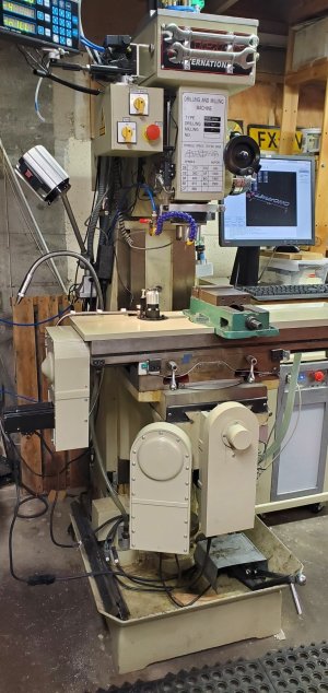

Looks good!Well the paint is finally hard enough (no longer tacky) so I can handle the rest of the parts. Now all installed.View attachment 70099
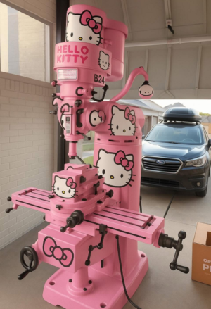
Not a chance. I have book on 101 things to do with a dead cat.You not limited to Cream colour you know be adventurous!
View attachment 70112

Tremclad new colours!You not limited to Cream colour you know be adventurous!
View attachment 70112
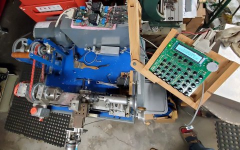
So the last week and a bit have had me immersed in project #42. I finally got around to adding the PIC32MK1024MCM processor onto the new board which plugs into the old sockets on the original ELS 8bit PIC18F processor.
Aside from some hardware mistakes in the layout where I should have done things differently jumper wires solved those problems.
The software... well that's another story. When I made the first test system for this project I stayed with the original Microchip C compiler and the 8 bit software translated to 32 PIC32MK795 bit so easily I was really shocked.
Fast forward four years and the desire to have hardware quadrature encoder capabilities means using a different PIC32. What I didn't realize at the time is that the now discontinued C32 compiler from Microchip did not support that newer device so I had to move to the XC32 compiler. Yuck!
Talk about breaking software. It's taken over a week to figure out all the issues that didn't work but tonight I was able to run threading passes on the Gingery Lathe. This is with the 1 PPR sensor just like the original ELS.
Coming up will be quadrature encoder support for better speed regulation. Also something like the LinuxCNC spindle/axis tracking that is used for power tapping and threading under LinuxCNC. And if I can get that working the USB connector on the add-on board will be able to read G-Code files which means some simple completely automatic operations.
OTOH, I still have 42 projects on the list so this one may be called complete once it can read a quadrature encoder.
Aside from some hardware mistakes in the layout where I should have done things differently jumper wires solved those problems.
The software... well that's another story. When I made the first test system for this project I stayed with the original Microchip C compiler and the 8 bit software translated to 32 PIC32MK795 bit so easily I was really shocked.
Fast forward four years and the desire to have hardware quadrature encoder capabilities means using a different PIC32. What I didn't realize at the time is that the now discontinued C32 compiler from Microchip did not support that newer device so I had to move to the XC32 compiler. Yuck!
Talk about breaking software. It's taken over a week to figure out all the issues that didn't work but tonight I was able to run threading passes on the Gingery Lathe. This is with the 1 PPR sensor just like the original ELS.
Coming up will be quadrature encoder support for better speed regulation. Also something like the LinuxCNC spindle/axis tracking that is used for power tapping and threading under LinuxCNC. And if I can get that working the USB connector on the add-on board will be able to read G-Code files which means some simple completely automatic operations.
OTOH, I still have 42 projects on the list so this one may be called complete once it can read a quadrature encoder.
Attachments
So in keeping with the spirit of the thread "METAL LATHE SMOKE, RPM LOSS, NEW LATHE MOTOR?" I thought I'd post my latest results on the ELS upgrade.
It's working fine when I poll the index sensor in the general 20kHz interrupt routine. RPM reports correctly and the lathe works just fine.
However, once I start using that input as an interrupt on rising edge with it's own interrupt I see something strange that I didn't see before.
The yellow trace is from the waveform generator creating an active low pulse.
The blue trace is after the signal conditioning and is the signal presented to the processor external interrupt input pin.
The green signal is an output that is set high when the interrupt routine is entered and set low when the code exits. There is a 5uS delay inside this routine to make the pulse wide enough to see clearly.
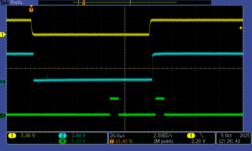
So why are there two green pulses when there should only be one when the blue signal goes high?
It's due to electrical noise showing up on the output of the blue signal conditioning. And it only happens when the keys are pressed or the display is being updated.
And it only happens with the PIC32 board installed. With the PIC18F there is no noise. As far as I can track it the changing of the ports on the PIC32 from input to output and back during keypad scanning and writing out to the LCD display causes some sort of noise pulses.
It can look as bad as this. Any time the buffered index signal is low the noise results in a massive number of pulses into the interrupt pin. The screen capture just barely shows the blue pulses but they are there.
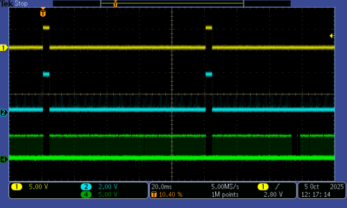
Totally perplexed. I've rerouted power. Added filter caps. Slowed down timing for the change from input to output to input etc. I may have to bail on this project.
It's working fine when I poll the index sensor in the general 20kHz interrupt routine. RPM reports correctly and the lathe works just fine.
However, once I start using that input as an interrupt on rising edge with it's own interrupt I see something strange that I didn't see before.
The yellow trace is from the waveform generator creating an active low pulse.
The blue trace is after the signal conditioning and is the signal presented to the processor external interrupt input pin.
The green signal is an output that is set high when the interrupt routine is entered and set low when the code exits. There is a 5uS delay inside this routine to make the pulse wide enough to see clearly.
So why are there two green pulses when there should only be one when the blue signal goes high?
It's due to electrical noise showing up on the output of the blue signal conditioning. And it only happens when the keys are pressed or the display is being updated.
And it only happens with the PIC32 board installed. With the PIC18F there is no noise. As far as I can track it the changing of the ports on the PIC32 from input to output and back during keypad scanning and writing out to the LCD display causes some sort of noise pulses.
It can look as bad as this. Any time the buffered index signal is low the noise results in a massive number of pulses into the interrupt pin. The screen capture just barely shows the blue pulses but they are there.
Totally perplexed. I've rerouted power. Added filter caps. Slowed down timing for the change from input to output to input etc. I may have to bail on this project.

So why are there two green pulses when there should only be one when the blue signal goes high?
My first thought is that it's due to an overflow. The system sits there waiting for a signal that doesn't come within the alloted time so it generates one just so it can exit the loop. Sort of like an error reset. If things don't happen when they should, or if the system doesn't receive an expected all good signal, the system resets.
But when you say that it only does this when you get noise or a button is pushed, that kinda says otherwise.
What kind of noise triggers it?
One has to understand the circuit in order to see perhaps what is happening.My first thought is that it's due to an overflow. The system sits there waiting for a signal that doesn't come within the alloted time so it generates one just so it can exit the loop. Sort of like an error reset. If things don't happen when they should, or if the system doesn't receive an expected all good signal, the system resets.
But when you say that it only does this when you get noise or a button is pushed, that kinda says otherwise.
What kind of noise triggers it?
Original PIC18F
One port is used as a bi-directional port to both write to a data latch, write commands/data to the LCD display and read LCD status ready and key button status. The port is 5V compatible and connects directly to the various components. Reading the keys is done through a buffer that is high impedance except when selected.
Now for the PIC32 there is a set of level translation buffers in between the PIC32 and the PIC18F connection.
Say the system is set up to read from the keypad.
So the PIC32 port is configured as an input.
The direction of the level translation device is also from the PIC18F data bus towards the PIC32.
Now we want to write out to the LCD display.
First the level translator is changed to become an input at the PIC32 side and output to the PIC18F data bus.
-- We have now two inputs connected together as the PIC32 is still an input.
Then change the PIC32 port to become an output.
-- This translates the 3V PIC32 signals out the level translator to 5V levels.
Data is latched out and presented to the LCD display.
The appropriate RS, E and RW lines are toggled to send data to the display.
-- This is usually more than just one character since we'll have a XY address and position command along with up to 40 characters.
And for some reason all this activity is creating noisy 1.5V spikes on the spindle sensor input, often just high enough to cause an interrupt. If I take out all the extraneous debugging and delays the actual interrupt routine as marked by the bCHARGE_Pump output pin which is the green trace. Time inside the interrupt routine is 280 nS. Very short.
C:
static void EncoderIndexCallback(uint32_t status, uintptr_t context) {

    bCHARGE_Pump = 1;    // A way to see approximately how long int32 interrupt routine takes.
    // The SpindleClockValue is incremented every once 50uS while the spindle is turning.
    SpindleClocksPerRevolution = SpindleClockValue;
    SpindleClockValue = 0;   // reset for the next full turn of the spindle.
    // Let Device Driver know there's a new RPM.
    fUpdatedRPM = 1;
    // And that we saw the sensor.
    fSpindleInterrupt = 1;
    // And that the spindle has started moving again.
    fSpindleTurning = 1;
    bCHARGE_Pump = 0;
}
And here you can just see that spurious pulse in the middle, not nearly as high a value as the actual signal level. It could be as simple as a poor layout issue.
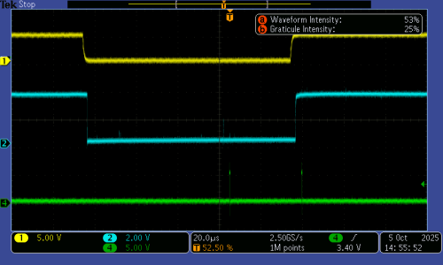
Perhaps I need a series of pull down resistors on the data bus signals to avoid noise pick up when the PIC32 and the level translator are both set as inputs.
Milling machine and CNC topic.
When David, Paul and Joni were over the other day I was demonstrating the probing and tool setting feature forgetting of course that the tool setting feature didn't work. Put a dimple in the vise and a small chip off the tip of a bevel tool bit.
Anyway so now I've been spending time writing up a detailed explanation on how the G-Code for the probe and tool setter actually work so that I can better understand the routines and fix the problem. It's going well and one of the sections is on how to measure the distance from the bottom of the quill to the table.
That number is required in order to measure the length of the touch probe just as the switch closes. The length of the probe is then entered into the tool table for tool T99 and also into the .INI file. In my case when the visitors were there I found out later that the value in the tool table did not match the value in the .INI file.
When the values don't match and a tool is measured and then brought to the 0.000 position as indicated by the probe the two values don't match up. Oops.
To measure the quill to table I home the machine. Move the table to a specific XY position and then move the knee up until i can just, with friction, move two stacked 1-2-3 blocks (4") under the quill. That value in machine coordinates was 8.704 and add in the 4" means max distance from machine Z home to bottom of quill is 12.704". At least that was the value in the ini file.
Measured today after 3 machine power off/on and homing cycles was:
12.7140", 12.7164" and 12.7170"
Aside from the 0.003" difference there's also the 0.010" to 0.014 difference from what was in the .INI file.
This value is critical in determining the length of the probe and also the height of the tool setter. So it appears I have a mechanical problem that needs to be solved.
1. Could be the home switch which is a roller switch actuated by the side of the knee.
2. Could be that the slop in the bevel gear drive to move the knee down and the retry after the first actuation results in the knee sticking ever so slightly.
I'm going with number 2 since often when the knee is on the way down I can hear the bevel gears rattling. I guess I need to add this to the list of 42 projects.
The belt drive turns the ball nut while the ball screw is fixed to the knee assembly.
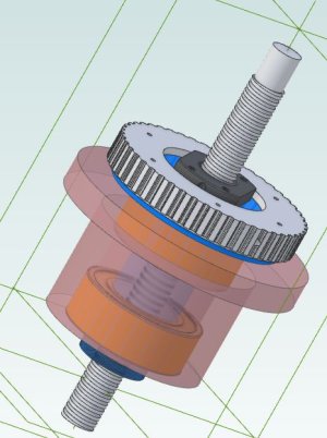
The ball nut holder is a spindle sitting in two angular contact bearings held with two nuts (not shown).
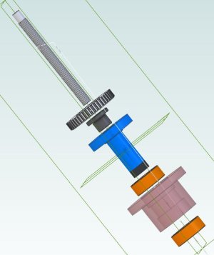
However to make all this fit I have to replace the ACME screw pedestal with a custom one that fits the ball screw assembly.
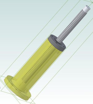
All in all not a small project I think. The motor will mount vertically with a belt and tension adjustment. Never did that drawing model yet and this idea is all now more than 4 years ago.
When David, Paul and Joni were over the other day I was demonstrating the probing and tool setting feature forgetting of course that the tool setting feature didn't work. Put a dimple in the vise and a small chip off the tip of a bevel tool bit.
Anyway so now I've been spending time writing up a detailed explanation on how the G-Code for the probe and tool setter actually work so that I can better understand the routines and fix the problem. It's going well and one of the sections is on how to measure the distance from the bottom of the quill to the table.
That number is required in order to measure the length of the touch probe just as the switch closes. The length of the probe is then entered into the tool table for tool T99 and also into the .INI file. In my case when the visitors were there I found out later that the value in the tool table did not match the value in the .INI file.
When the values don't match and a tool is measured and then brought to the 0.000 position as indicated by the probe the two values don't match up. Oops.
To measure the quill to table I home the machine. Move the table to a specific XY position and then move the knee up until i can just, with friction, move two stacked 1-2-3 blocks (4") under the quill. That value in machine coordinates was 8.704 and add in the 4" means max distance from machine Z home to bottom of quill is 12.704". At least that was the value in the ini file.
Measured today after 3 machine power off/on and homing cycles was:
12.7140", 12.7164" and 12.7170"
Aside from the 0.003" difference there's also the 0.010" to 0.014 difference from what was in the .INI file.
This value is critical in determining the length of the probe and also the height of the tool setter. So it appears I have a mechanical problem that needs to be solved.
1. Could be the home switch which is a roller switch actuated by the side of the knee.
2. Could be that the slop in the bevel gear drive to move the knee down and the retry after the first actuation results in the knee sticking ever so slightly.
I'm going with number 2 since often when the knee is on the way down I can hear the bevel gears rattling. I guess I need to add this to the list of 42 projects.
The belt drive turns the ball nut while the ball screw is fixed to the knee assembly.
The ball nut holder is a spindle sitting in two angular contact bearings held with two nuts (not shown).
However to make all this fit I have to replace the ACME screw pedestal with a custom one that fits the ball screw assembly.
All in all not a small project I think. The motor will mount vertically with a belt and tension adjustment. Never did that drawing model yet and this idea is all now more than 4 years ago.
Some testing but of course at only one bevel gear contact position. Nothing says that any of the other bevel surfaces are as accurate.
Backlash is set to only 0.0042" believe it or not.
Jogging 0.001" per step with the MPG or using G-Code like:
F10 (or even F60)
G1 Z0.010
G1 Z-0.010
G1 Z0
And from 1" away back to Z0.010 with G1 Z0.010 in each case has no error.
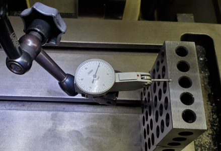
I guess to do this right I need to count how many teeth are on the bevel gear and move the Z axis one half and then a full tooth and reset the Z zero position for each and again test backlash. Although how I'd ever use that information in the .INI file I don't know.
Originally the shaft rode in a bronze (I think) bushing and there was lots of end play. I created a bearing holder:
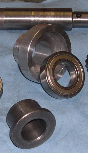
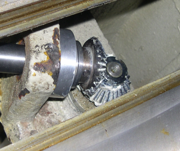
And now this is what it looks like now including the original radial thrust bearing which results in the 0.0042" backlash.
Maybe it is the home switch?
Backlash is set to only 0.0042" believe it or not.
Jogging 0.001" per step with the MPG or using G-Code like:
F10 (or even F60)
G1 Z0.010
G1 Z-0.010
G1 Z0
And from 1" away back to Z0.010 with G1 Z0.010 in each case has no error.
I guess to do this right I need to count how many teeth are on the bevel gear and move the Z axis one half and then a full tooth and reset the Z zero position for each and again test backlash. Although how I'd ever use that information in the .INI file I don't know.
Originally the shaft rode in a bronze (I think) bushing and there was lots of end play. I created a bearing holder:
And now this is what it looks like now including the original radial thrust bearing which results in the 0.0042" backlash.
Maybe it is the home switch?
Here's the original set of parts. Zooming in I count 25 teeth on the bevel gear. The Knee ACME Lead Screw is 4 TPI.
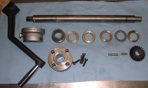
So one lead screw turn is 0.250" and each tooth then represents 0.010" of motion. My guess is uneven wear would likely not cause a full 0.010" difference in position. But I may be missing something.
So one lead screw turn is 0.250" and each tooth then represents 0.010" of motion. My guess is uneven wear would likely not cause a full 0.010" difference in position. But I may be missing something.
Here's the entire mechanism when it was still run with a stepper motor simply give me power feed on the knee. The handle fit so badly on the shaft moving the knee up and down was tedious. Using an older ELS to drive the knee motor suddenly made using the knee simple.
Getting rid of all of this would be so nice.
Getting rid of all of this would be so nice.
Attachments
If there is any variability in the position of the home switch; loose mounting, loose trigger, old switch, that could contribute to the difference as the knee would be starting from a slightly different home position each time.
Last edited:
I think for now I can put the bevel gear and backlash aside. I changed the height of the 1-2-3 blocks by 0.125" (half turn of the lead screw and other side of the bevel gears)
Same set of tests. This time repeatability in one direction had zero error. In the other direction short by 0.0005". At this point in time, not enough to worry about.
Time to look at home/limit switch repeatability.
Same set of tests. This time repeatability in one direction had zero error. In the other direction short by 0.0005". At this point in time, not enough to worry about.
Time to look at home/limit switch repeatability.