• Scam Alert. Members are reminded to NOT send money to buy anything. Don't buy things remote and have it shipped - go get it yourself, pay in person, and take your equipment with you. Scammers have burned people on this forum. Urgency, secrecy, excuses, selling for friend, newish members, FUD, are RED FLAGS. A video conference call is not adequate assurance. Face to face interactions are required. Please report suspicions to the forum admins. Stay Safe - anyone can get scammed.

JCDammeyer's 42 projects

Well. Just finished assembling 45 of these.
RIMAssemblyParts.jpg


Now to finish 20 of the little boards for this version. The main set of 20 are already done.
GIM1.jpg


Waiting for the small DIP relays that should arrive tomorrow which means I can finally get back to the air compressor cooler installation. Tomorrow the Thermisters will also arrive so I can measure inlet/outlet temperatures. The above module with two small DIP relays is set up for two Thermisters so I have something ready to go to read those temperatures and the pressure sensor.
Have to read up again on using the bender and the Right and Left markings as to where to do the bend.
 
I have some of these Thermistors coming tomorrow. The A2 size so a 3mm hole in something to get it into the compressor cooler inlet and outlet air stream.
1717567580476.webp


I can see drilling a hole into a brass fitting and cementing it in with epoxy. Part of the problem is the heat on the inlet side. Epoxy gets soft when warm and it's under pressure. But this would work.

And then at the radiator end the fittings have that 74 degree flare and it's just a nut on the flared tube that connects. At the compressor end it's a double flare fitting again with a nut on the flared tubing.

I could just clamp the thermistor tubing and wrap insulation around that. Since the tubing does get hot eventually the inlet and outlet temperatures would stabilize.

Pressure transducers also arrived today. That will be at the tank end. I also got a box of CDS resistors (sensing light) which hopefully will add the control to keep the compressor from running if the shop lights are off.

Anyway, suggestions on how to mount the Thermistors are welcome.
 
You have a pretty high vibration environment with pretty extreme temperature cycles. I don't think HT epoxy will last long term;

What I would do is to put a T in the line with about a 2" diversion. This can then be made removable for replacement, and is filled with silicone sealant, potting the wires. the sensor can extend into the flow of the air...

sensor sealing.webp
 
Are there T's with 1/2" OD for copper tubing? Don't mind soldering something in once I have the tubing bent and formed to fit the path.
If I have to use a flared tube to flared tube fitting I can then drill a small hole, solder in a small tube into one of the wrench flats. I'm guessing the suggestion from @Dabbler means that silicone in a longer tube will withstand the air pressure.
Can you buy or make a probe housing, along the lines of the ones used for thermocouples? Some heat transfer compound inside, and the thermistor never needs be in the actual pressure passage.
 
I'm thinking something like this might work. Soldered onto the 1/2" OD tube and then some sort of removable fitting on the T.
1717609227046.webp
 
Looks good. You would have to solder a NPT fitting onto the 1/4" leg... I have seen them but I don't know where to by them.

@Susquatch is right... the 2" length of the potting compound has a lot of surface area to bond to. One could even neck the end, so there is also compressive strength as well as shear strength.....

This would replaceable, but foolproof....
 
Last edited:
I think I have a solution.

1717618372533.png


edit: Specifically years ago I bought a hand oil pump for the mill. It's not on the mill yet but is on the project list. (I'm sure everyone can guess which project # it is.).
Anyway, I've ordered the 1/2" OD T fittings with the 1/4" outlet and once they arrive I'll see how to mount the 1/8" tubing connector to it.
I'll go with the @Dabbler method and fill the tube with silicone and flatten the end a bit. My little modules like the Generator Interface Module (GIM) has two Thermister Inputs, Analog Inputs for the pressure transducer and CDS light detector. Also relay drivers and even PWM 0-10V outputs if I need to add additional FAN cooling.
The module uses CANOpen protocol on CAN bus and I can pull those messages out and show them on my LinuxCNC desktop. Or one of these days actually create a CANOpen Display Module that shows the values.
 
Last edited:
Here we go. First half. Very happy with the pump double flare. Not so happy with the 74 degree cooler flare. My clamp kind of crimped the tube and the flare as a result didn't come out looking great. But once the 1/2" to 1/4" to 1/2" T adapters arrive tomorrow I can always do something to redo that once flare. But I think I'll wait till the other half is done so I can test for leaks first.
1717653987983.webp
 
Mounting temperature transducers tends to be messy. At some point I used a stud mounted sensor available from D.K. for a thermostat project in New York, I can look it up when I get home presently enjoying the 30deg sunny days at the cottage;-)

Until then one possible solution see image below.

When hand soldering SMT, I'm fine with 0603, 0402 are okay in small quantities. Smaller than that ie. 0201 no hand soldering I tried once (only automated) when I look under the microscope 0201 are smaller than table salt, one sneeze and you just lost a 100 of them. I designed 0201 circuits for various prosthesis.

I use Metcal soldering stations for hand soldering (love them). My smallest tip IIRC is 1mm? looks like a shovel under the microscope. Metcal does sell 0.25mm tips.

The cool thing about designing those tiny circuits is that there is little difference for the designer when using a nice big monitor, however not every fab house is capable/reliable with that density.
1E05B5E4-1C80-4274-A541-B526B646FD0F.jpeg
 
Last edited:
Back home now, sun is gone, rain today;-)

Stud mount thermistor: https://www.digikey.ca/en/products/...206?s=N4IgTCBcDaICwE4CsBaA7ABjQRhQOQBEQBdAXyA

Small components, earlier I stated 0201 is smaller than table salt crystal, however I was actually thinking about the 01005 resistors I used on a project they are 0.4 x 0.2mm, I snapped an image next to an 0805 (2 x 1.2mm), the 01005 is smaller than a single digit of the 0805 resistor pretty darn small and too small to hand solder even with a steady hand.

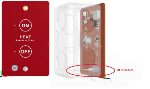
Second image is the thermistor, PCB mounted for a thermostat of sorts.
small.png


Heat.png
 
Last edited:
The 01005 are frightening. They make sense - on a modern CPU you have hundreds of power domain (ground and voltage) pins on a ball-gate-array. In theory you need the bypass/filter capacitors, and any other related RC logic, "as close as possible" to the pin. As at the frequencies and low voltages in play that means *close*. That means stuffing hundreds of these in the space on the other side of the board, while dodging the other pins and wires.
Just frightening the knock-on effects of smaller transistor processes and bigger chips.
 
Last edited:
Just frightening the knock-on effects of smaller transistor processes and bigger chips.
So true, IIRC this uC has about 900 pins and even with signals traveling at near the speed of light, we need to match the lengths of traces going to say a memory chip, so the signals arrive at the same time. This was a bit of a tricky layout. If you see one of those big windmills turning, chances are one of these might be controlling it.
HighSpeedLayout.jpg
 
Last edited:
Well how about that. What Amazon.ca said they were selling actually was delivered and matched the dimensions.
1717725227732.png


The fittings for the 1/8" tubing are too large but one of the two circled could be turned down and soldered into the top of the copper T fitting. Need to find a few more of those first since they were destined for the mill oiler.

I'm not sure what the 5 at the top there are for. The 1/8" tube slides right through but the bag also has the small compression washers.

1717726013219.png


I think these will be fine.
 
Well how about that. What Amazon.ca said they were selling actually was delivered and matched the dimensions.
View attachment 48526

The fittings for the 1/8" tubing are too large but one of the two circled could be turned down and soldered into the top of the copper T fitting. Need to find a few more of those first since they were destined for the mill oiler.

I'm not sure what the 5 at the top there are for. The 1/8" tube slides right through but the bag also has the small compression washers.

View attachment 48527

I think these will be fine.
Oops. I ordered for delivery on Saturday the ones like the one on the right. Except the hole is to too large and after I turn down the threads to 1/2" diameter there's not much metal left. As in the hole is 0.215" so 0.020" wall thickness. Assuming I get it centered on the lathe.

Can't find ones with the smaller hole online at the moment.

1717729352073.webp


I had planned on soft soldering these into the copper T. I suppose if I silver solder a piece of brass in first and then turn it to 0.25" the soft solder won't melt the silver solder and the part should say stable. The hole down the middle only needs to be about 3mm.
 
The hole is 3.2mm. Made it a bit longer so it's easier to only apply the silver solder to the outside. Once soldered I think it should be possible to turn the outside down to 0.25 so it can be soft soldered into the copper.

1717731583055.webp


However, not tonight I think. I'll wait for suggestions in case I'm making this way too complicated.
 
Back
Top