-
Scam Alert. Members are reminded to NOT send money to buy anything. Don't buy things remote and have it shipped - go get it yourself, pay in person, and take your equipment with you. Scammers have burned people on this forum. Urgency, secrecy, excuses, selling for friend, newish members, FUD, are RED FLAGS. A video conference call is not adequate assurance. Face to face interactions are required. Please report suspicions to the forum admins. Stay Safe - anyone can get scammed.
-
Several Regions have held meetups already, but others are being planned or are evaluating the interest. The Calgary Area Meetup is set for Saturday July 12th at 10am. The signup thread is here! Arbutus has also explored interest in a Fraser Valley meetup but it seems members either missed his thread or had other plans. Let him know if you are interested in a meetup later in the year by posting here! Slowpoke is trying to pull together an Ottawa area meetup later this summer. No date has been selected yet, so let him know if you are interested here! We are not aware of any other meetups being planned this year. If you are interested in doing something in your area, let everyone know and make it happen! Meetups are a great way to make new machining friends and get hands on help in your area. Don’t be shy, sign up and come, or plan your own meetup!
You are using an out of date browser. It may not display this or other websites correctly.
You should upgrade or use an alternative browser.
You should upgrade or use an alternative browser.
JCDammeyer's 42 projects
- Thread starter jcdammeyer
- Start date
The critical bore is at the thin end, not the flange end.Actually why couldn’t you use the tailstock to make it then bore it in a second operation after cutting to length?
This is what I need to make
I'd rough cut it to length on the band saw with say 1/4" extra. Then machine the back of the large diameter flange first. The only dimension that really matters in this op is the flat rear surface. The OD can be cut too, but I prolly wouldn't because of the stick out. Gronk on the Jaws. Don't worry about marring your aluminium bar. That will get machined off later. This will be a facing operation only for the backside of your part at the big flange. Then I'd remove it from the lathe and drill and tap sacrificial flange holes from the back side small enough to be able to be drilled out later to the final required hole size. Next, I'd make a steel arbour out of 1/2" flat plate and mill flats in it for the lathe Jaws to hold solidly. The plate then needs to be mounted in the Jaws so the plate sits proud of the Jaws so it can be faced flat and true to the spindle. It also needs a center hole bigger than your final part ID. Mark the plate and jaws so the plate can be reinstalled later in the same place. Then remove it and drill it for the same bolt pattern as your part. Maybe with recessed countersinking so the screw heads don't hit the lathe jaws.
Now you can bolt the two parts together solidly with a flat 1/8" sacrificial aluminium "gasket" between them. If you want, you could also pin them - your call on whether the extra hole matters. The pin holes can be drilled as an assembly because the objective is a solid one piece assembly. All the bolts and pins must be short enough so they don't interfere with cutting the inside flange face later.
The sacrificial aluminium 1/8" plate between the two parts will let you cut the flange OD later without worrying about hitting the steel back plate.
Mount this Assembly back on the lathe with the steel plate in the same location as it was before.
You already know the rest.
You could optionally cut a big steel bar to do the same thing but act like a mandrel. But I'd use a plate myself. In either case, the key to all this is two flat surfaces (one in the steel plate and one on the back of your part) that are both perpendicular to the lathe axis. Once you dial those flats in, the rest will naturally machine concentricly to the spindle even if it wobbles to begin with. Just get those flats square.
You can drill a center in the long part to use while you machine the external surfaces, but I don't think it's necessary.
If you later find that the rear face is not concentricly square, you can always dial the part in on a 4 jaw with jaw pads and touch up the face.
The key to all this is a steel mandrel plate strong enough to hold your part for all the required operations without messing up your aluminium part getting clamped in the chuck jaws.
Machining the through hole will be a trick cuz of the length. But that will be what it will be. I'd drill it first, then use the biggest boring bar that fits tto machine the small end - which is a critical dimension if I understood correctly.
Broaching the bore will be what it is. I don't envy you that broaching job.
I'll think about it a bit more and see if I can come up with a better method, but I'm happy with this approach.
I decided to take the next step for modelling the parts rather than just CAD. Measuring with my caliper the spindle part is the correct length but when all assembled is too short. Possibly when the bearings are compressed really tightly the thickness is 16.25mm but with the calipers I get about 16.28mm.
I think the ring that separates and serves as the bottom of the bearing seat is too thick because going through all the drawings that spindle part should stick out past the inner bearing race by about 1.6mm. Instead it's short by about that.

So the discussion on how to bore the bearing race seats so they are coaxial and to the right depth is going to be the interesting part of this project. When assembled with the short piece of arm as shown above it looks like this: The motor clamp lying flat requires that the planetary gear assembly needs to be taken apart. Don't really like that idea so I may redesign that one too.

Off to pick up some more white filament. Then reprint that bottom piece since the metal version has a cut-out while the supplied STL file does not.
I think the ring that separates and serves as the bottom of the bearing seat is too thick because going through all the drawings that spindle part should stick out past the inner bearing race by about 1.6mm. Instead it's short by about that.
So the discussion on how to bore the bearing race seats so they are coaxial and to the right depth is going to be the interesting part of this project. When assembled with the short piece of arm as shown above it looks like this: The motor clamp lying flat requires that the planetary gear assembly needs to be taken apart. Don't really like that idea so I may redesign that one too.
Off to pick up some more white filament. Then reprint that bottom piece since the metal version has a cut-out while the supplied STL file does not.
I decided to take the next step for modelling the parts rather than just CAD.
Sorry about my earlier post. I must have misunderstand your question.
No misunderstanding. I still have to make the spindle part out of metal. But it's boring the hole that holds the two tapered rollers to the right depth and a press fit that should be interesting.Sorry about my earlier post. I must have misunderstand your question.
No misunderstanding. I still have to make the spindle part out of metal. But it's boring the hole that holds the two tapered rollers to the right depth and a press fit that should be interesting.
Are they at both ends? I didn't see that in your drawing. If so, it's an easy modification of the process.
Here's the drawing.Are they at both ends? I didn't see that in your drawing. If so, it's an easy modification of the process.
Attachments
OK. So I decided I'd leave the big long piece in the chuck and bore to 14.01mm as per the drawing and then use the live centre to hold things while turning the outside. Here are two thumbnail photos.
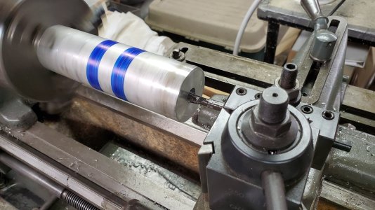
Last few passes were less than 0.001" cut, 0.003" pitch at 360 RPM. The motor shaft slides in smoothly and when removed makes a slight pop sound so it's a very close but not binding fit. I then added a 30 bevel to the edge and started on reducing the diameter.
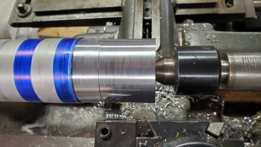
Same RPM, set ELS to do 0.010" pitch and 0.015" depth of cut turn from face to 2.19". Surface finish isn't too bad. Squirt WD-40 on it and there's just a tad bit of smoke so it's not too hot.
Supper time now. I'll finish later. Target diameter is 30mm so I'll use one of the bearings to also ensure a very close almost friction press fit.

Last few passes were less than 0.001" cut, 0.003" pitch at 360 RPM. The motor shaft slides in smoothly and when removed makes a slight pop sound so it's a very close but not binding fit. I then added a 30 bevel to the edge and started on reducing the diameter.

Same RPM, set ELS to do 0.010" pitch and 0.015" depth of cut turn from face to 2.19". Surface finish isn't too bad. Squirt WD-40 on it and there's just a tad bit of smoke so it's not too hot.
Supper time now. I'll finish later. Target diameter is 30mm so I'll use one of the bearings to also ensure a very close almost friction press fit.
Here's the drawing.
This isn't the same part.
I was replying to your machining question request for suggestions in post 291.
I see you are back to that part again above. The problem with starting on the small end is marring the finish with the Jaws when you switch to working on the flange end. It's only aluminium and it's too big to hold close to the working surface. That's why I suggested making a steel arbour to hold it from the flat on the flange. That will allow you to work on the entire length without marking any surfaces.
Turned out not to be a problem. I turned the outside without incident and the bearings are an incredibly close and smooth fit.This isn't the same part.
I was replying to your machining question request for suggestions in post 291.
I see you are back to that part again above. The problem with starting on the small end is marring the finish with the Jaws when you switch to working on the flange end. It's only aluminium and it's too big to hold close to the working surface. That's why I suggested making a steel arbour to hold it from the flat on the flange. That will allow you to work on the entire length without marking any surfaces.
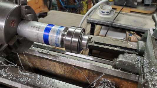
Then cut it off just proud of the flange dimension.
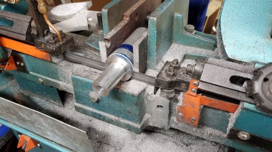
Held it in the 3-jaw with minimal pressure and then concentrated so much on boring the relief hole to be able to clear the broach for the motor shaft key that I forgot to take photos. The shaft was not marked up.
Next step, the holes which I may just do with the rotary table and then broach the key way.
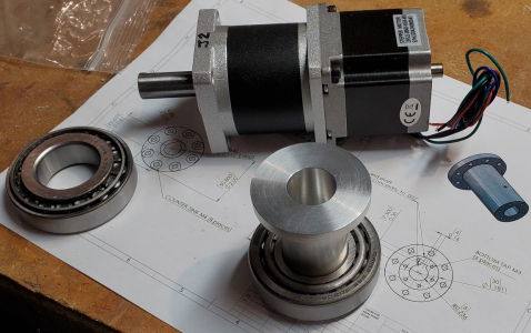
The hole I bored for the motor now seems looser than before. I made sure the part had cooled before the final fit. Won't really know until I have the keyway and clamping set screw and then I can see how much run out there is. That will be the ultimate test.
I am having a bit of trouble believing that the gear box clamping bracket/plate is going to hold that long pink arm with the various motors and drives on it from rotating at the gear box. The post #271 has this bracket somewhat towards the center of the gear box, the plate appears to be about 3/8inch thick with a single clamping screw. Am I missing something, or is the arm(pink) and attached equipment alot smaller and lighter then it looks to be?
As to boring the tapered bearing mount with the shoulder in the hole, I have thought of mounting it on a mill table raised on spacer blocks. Get it aligned, do a face cut over the whole surface, then bore shoulder I.D completely though it. Now bore bearing O.D. to depth for the upper bearing. Turn over piece, use shoulder I.D. to line up for boring the second bearing I.D. to depth. I think a face cut on this side if done would have to allow for amount removed to be added to boring depth of bearing hole, as I would do the face cut after the boring to try and make sure nothing changed.
An idea, I am sure there are some others also. LOL.
Can the flange on the gear box be turned in a lathe to the gear box diameter, appears the gear box maybe able to be removed from the motor without having to open gear box. This would make the gearbox possibly unusable for a future project, but??
Last edited:
The main mounting is actually the 4 screws through the motor plate. The bracket is only supposed to be lightly clamped around the black part of the reduction gear assembly and that's probably more just to hold things from wobbling? Normally you'd bolt this assembly at the reduction shaft end plate and the rest of the motor and gear assembly would just sit there.I am having a bit of trouble believing that the gear box clamping bracket/plate is going to hold that long pink arm with the various motors and drives on it from rotating at the gear box. The post #271 has this bracket somewhat towards the center of the gear box, the plate appears to be about 3/8inch thick with a single clamping screw. Am I missing something, or is the arm(pink) and attached equipment alot smaller and lighter then it looks to be?
It's not possible to run screws and nuts through the reduction gear flange (unless maybe countersinking the flange) because the space between that flange and the J2TensionRing plate is very small. It has to be to get the keyed shaft in deep enough past the tapered bearing for a set screw to bear down on the motor shaft key. And even then the set screw is right on the end of that key.
Hopefully this photo shows hot tight it is at the end of that planetary gear box to the J2 Tension Ring.
But I think Countersinking the end plate and using really long screws could work if it was required. Apparently it isn't.
Your approach for boring the holes and keeping them aligned is the direction I was going. Could even be done on the lathe faceplate. Then flipping it over onto a bearing sized centering hub would keep it perfectly aligned. Probably more accurate than lining up that centering hub on the mill tableAs to boring the tapered bearing mount with the shoulder in the hole, I have thought of mounting it on a mill table raised on spacer blocks. Get it aligned, do a face cut over the whole surface, then bore shoulder I.D completely though it. Now bore bearing O.D. to depth for the upper bearing. Turn over piece, use shoulder I.D. to line up for boring the second bearing I.D. to depth. I think a face cut on this side if done would have to allow for amount removed to be added to boring depth of bearing hole, as I would do the face cut after the boring to try and make sure nothing changed.
I'm thinking instead to redesign the clamp plate to have two screws like the rod end on an engine. The two screws would be outside the 4 motor mount screws. Have to model it first. I'll post the drawing when I've done that.An idea, I am sure there are some others also. LOL.
Can the flange on the gear box be turned in a lathe to the gear box diameter, appears the gear box maybe able to be removed from the motor without having to open gear box. This would make the gearbox possibly unusable for a future project, but??
I turned the shoulder on the lathe with the part held in the 5C collet. Then transferred the collet and part to the mill. Used my probe and LinuxCNC to find the center line and end.
Then simple G-Code commands to cut 0.025" depth at 3 IPM with 800 RPM spindle.
G1 Z-0.025 F60
G1 X-1.75 F3 S800 M3
G1 Z0 F60
G1 X0.2

Rinse and repeat with G1 Z-0.050 all the way to Z-0.325
After that at full depth a Y0.005 and Y-0.005 to widen the slot so the broach moves smoothly.
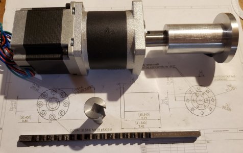
Clean up with file, Saw off and clean up face on lathe. Here's the commercial one I bought for 16mm way back and the 14mm one I just made.

What's really sad is I made this one again because the last one I made had an offset of about 0.039". Not sure why. I was so careful this time. Not sure whether it's an issue with Y axis backlash or the probe to find the center line is out but in either case once again I have about a 0.030" offset. I'm sure the 5C spin collet is parallel to the X. Unless it moved.

Going to have to try again. Sigh...
And yes, it would be easier to just buy one.
Then simple G-Code commands to cut 0.025" depth at 3 IPM with 800 RPM spindle.
G1 Z-0.025 F60
G1 X-1.75 F3 S800 M3
G1 Z0 F60
G1 X0.2
Rinse and repeat with G1 Z-0.050 all the way to Z-0.325
After that at full depth a Y0.005 and Y-0.005 to widen the slot so the broach moves smoothly.
Clean up with file, Saw off and clean up face on lathe. Here's the commercial one I bought for 16mm way back and the 14mm one I just made.
What's really sad is I made this one again because the last one I made had an offset of about 0.039". Not sure why. I was so careful this time. Not sure whether it's an issue with Y axis backlash or the probe to find the center line is out but in either case once again I have about a 0.030" offset. I'm sure the 5C spin collet is parallel to the X. Unless it moved.
Going to have to try again. Sigh...
And yes, it would be easier to just buy one.
Try #2 today, all in all Try #3.
This time I made darn sure after tightening down the 5C collet and then verifying that the part held in the collet was straight within about 0.0005"
Then I found the mid point with the probe and verified a different touch off and my Shumatech DRO. About 0.004" difference for where they thought the center was. I made a scratch pass along the top and it looked like it was centered.
Once I had the depth I measured from the edge to the outside on each side of the slot and then expanded the slot in the direction that was larger.
Ultimately I'm still off by about 0.007" but it's also a nice sliding fit so likely won't matter. And of course once it was done there was no point in waiting since the 3T arbour press was screaming at me "Use me, Use me".
One pass with the broach and then one pass with the thinner shim. Could have used a shim half the thickness but this is fine because the slight groove on the opposite end will help guide the drilling of the bolt circles which have to line up with the key.

Are there 'Distilling' experts on this forum? I wasn't able to look inside the upper section and the lady doing our teaching tour didn't really know the innards either. It's not quite the typical 'pot still' nor a thumper. The botanical ingredients for the classic gin were in a cloth bag (like a tea bag). We then weighed another 8gm of our own extras to create our unique flavour. They went into a second 'tea bag'. Both were dumped into the 500mL or so of 98% ethanol.New project #42. Dig out my wine and beer stuff along with the bits and pieces collected for the still and finish this one.
Made a custom bottle of gin outside Cardigan, Wales.
What was distilled was about 400ml of 86% gin flavoured alcohol. We then added distilled water to bring it down to 43%. Bottled 0.7L and poured a couple of shots, added tonic water and enjoyed the results.
The long thin tube along the side has the spiral tube with the vapour and is connected to the water supply. So for the most part it looks like a 'pot still'.
Are there 'Distilling' experts on this forum?
You are not fooling me. You are just trying to get the lady bombed..
My son gave me a book a few years ago when I was thinking about distilling my own whisky.
"The Compleat Distiller"
I bought a few more:
"How to Make Whisky"
"The Joy of Home Distilling"
"The Home Distillers Workbook"
I even have one of these bought many years ago.
But as yet haven't made the distiller hardware.

