-
Scam Alert. Members are reminded to NOT send money to buy anything. Don't buy things remote and have it shipped - go get it yourself, pay in person, and take your equipment with you. Scammers have burned people on this forum. Urgency, secrecy, excuses, selling for friend, newish members, FUD, are RED FLAGS. A video conference call is not adequate assurance. Face to face interactions are required. Please report suspicions to the forum admins. Stay Safe - anyone can get scammed.
-
Several Regions have held meetups already, but others are being planned or are evaluating the interest. The Calgary Area Meetup is set for Saturday July 12th at 10am. The signup thread is here! Arbutus has also explored interest in a Fraser Valley meetup but it seems members either missed his thread or had other plans. Let him know if you are interested in a meetup later in the year by posting here! Slowpoke is trying to pull together an Ottawa area meetup later this summer. No date has been selected yet, so let him know if you are interested here! We are not aware of any other meetups being planned this year. If you are interested in doing something in your area, let everyone know and make it happen! Meetups are a great way to make new machining friends and get hands on help in your area. Don’t be shy, sign up and come, or plan your own meetup!
You are using an out of date browser. It may not display this or other websites correctly.
You should upgrade or use an alternative browser.
You should upgrade or use an alternative browser.
DavidR8's shop shenanigans
- Thread starter David
- Start date
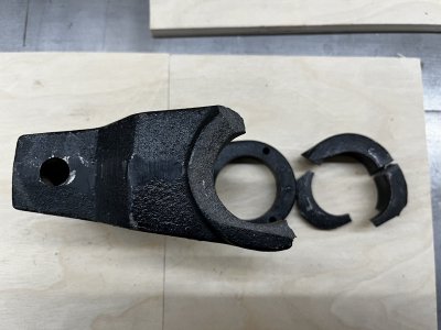
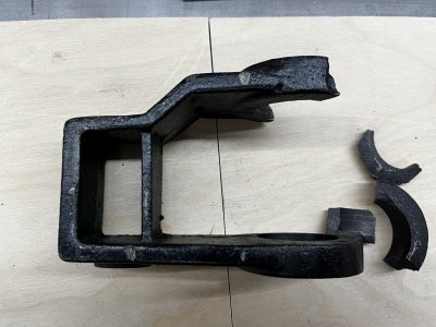
My initial plan is to plasma cut the two side pieces from 1/2" plate and bore the bearing holes.
Then do a trial assembly with the countershaft to get dimensions for the connecting pieces.
Make that and then tack it together with the countershaft in place to maintain some modicum of alignment.
Also considering making it from aluminum as it's not under high stress.
Definitely welcome your ideas 🙂
140mower
Don
I'm probably going about it wrong in my mind, but, I would be tempted to braze it back together, line bore it oversize, sleeve the two sides, then line bore back to spec. Although, if you can get a bearing that is a little bigger on the od, that might work as well.
If all that fails, then it's back to fabricating another....
If all that fails, then it's back to fabricating another....
Thanks Don, I've thought about brazing it together but I've never brazed anything.I'm probably going about it wrong in my mind, but, I would be tempted to braze it back together, line bore it oversize, sleeve the two sides, then line bore back to spec. Although, if you can get a bearing that is a little bigger on the od, that might work as well.
If all that fails, then it's back to fabricating another....
But by the same token I've never made anything like this before either so there's that. 😵
140mower
Don
This is the perfect opportunity to change all that. 😛Thanks Don, I've thought about brazing it together but I've never brazed anything.
Edited to add.....
I've seen several examples of your work in several different avenues, I am quite confident that brazing is well within your skill set. 🙄
You know. If you have a well equipped metal shop, welder, oxy-accet., wood working tools and a 3D printer then the solution is of course to 3D print the whole thing. Bearings included...😱
😉
😉
I have thought about making a 3D print to make a casting.You know. If you have a well equipped metal shop, welder, oxy-accet., wood working tools and a 3D printer then the solution is of course to 3D print the whole thing. Bearings included...😱
😉
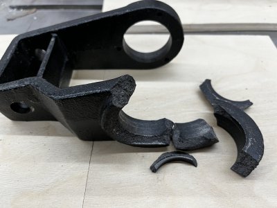
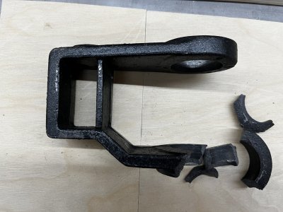
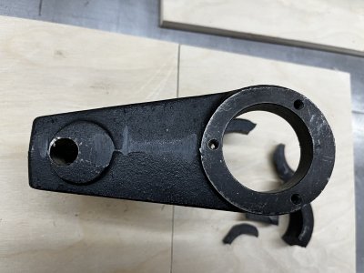
If you need to take dimensions there is easily enough of the broken side to get highly accurate dimensions for a new build, if that is in your wheelhouse. Brazing isn't that difficult to learn, and some practice on semi cast iron or malleable iron first would help a lot. that being said, taking all the dimensions and failing doesn't put you in a worse state than now.
OR -- you could take a leaf from @PeterT playbook (he had Keith Fenner fix his lathe, for a fee), and see if Keith Rucker would braze/repair it for you. His charges are runoured to be in the 'very reasonable' range. He also has the skill and equipment to assure the resulting bores are still in line and accurate. It would make a great video, but he's also chasing a bunch of projects right now. He is very good at brazing, and if done properly, it is stronger than the original part.
As to construction of a new part, the stresses on these components aren't mighty. This could be done as a no-weld bolt-together fabrication out of 1/2" cold rolled steel. Alignment can be done on the bearing seats by using your Colchester as a line bore to do it all in one setup after assembly.
- I'll check my assembled one to see what the clearance issues are.
Looking at the pieces, there are only three datum lines, and you have all of them.
Bearing o.d., you have one complete and a reference point at the remaining section of the broken socket
Distance of pivot arm to bearing center, and you have an unmolested bearing socket to measure from
Offset of pivot arm from broken bearing, and it’s probably not too critical.
I suspect it would be pretty straightforward to fabricate from welded steel and line bore the bearing sockets.
I love the idea of having Keith Rucker fix this.If you need to take dimensions there is easily enough of the broken side to get highly accurate dimensions for a new build, if that is in your wheelhouse. Brazing isn't that difficult to learn, and some practice on semi cast iron or malleable iron first would help a lot. that being said, taking all the dimensions and failing doesn't put you in a worse state than now.
OR -- you could take a leaf from @PeterT playbook (he had Keith Fenner fix his lathe, for a fee), and see if Keith Rucker would braze/repair it for you. His charges are runoured to be in the 'very reasonable' range. He also has the skill and equipment to assure the resulting bores are still in line and accurate. It would make a great video, but he's also chasing a bunch of projects right now. He is very good at brazing, and if done properly, it is stronger than the original part.
As to construction of a new part, the stresses on these components aren't mighty. This could be done as a no-weld bolt-together fabrication out of 1/2" cold rolled steel. Alignment can be done on the bearing seats by using your Colchester as a line bore to do it all in one setup after assembly.
- I'll check my assembled one to see what the clearance issues are.
Sadly he's six to nine months behind in projects.
He did give me some advice though which was to just make a new bearing holder from cast iron and then braze that onto the part.
Last edited:
The idea was *similar* to having Fenner do Peters shaft, by having Rucker braze your assembly - if he would do it. Rucker is an expert at brazing, especially compared to Fenner and others.I love the idea of having Keith Fenner fix this. Or did you mean Keith Rucker?
Rucker, will, of course charge you - if he will take it on - but ot takes any guesswork out of it for you. We can always measure mine if disaster occurs, but there is enough geometry to get all your dimensions from your current part.
That would be a heck of a lot easier than trying to braze all those pieces back together.He did give me some advice though which was to just make a new bearing holder from cast iron and then braze that onto the part.
I would use the bandsaw and cut following the arc of what's left of the bearing holder, that gives you more contact area for brazing.
If luck is on your side you might be able to find a piece of heavy wall cast pipe that could be made to work.Or what about making a bearing holder from steel and brazing that on.
One other option is to epoxy glue the pieces back together. Then apply wax to add tapers and make the machined areas smaller.
It's likely an iron foundry could then take that and cast you a new one. They might add a bit more wax to make things easier.
It's likely an iron foundry could then take that and cast you a new one. They might add a bit more wax to make things easier.
On the left is a bronze clevis link for a pulley block on Taleisin, the wooden boat built by Lin & Larry Pardy.
Larry added wax to fill in the worn part. I first cast a sample out of aluminum.

Then made 3 out of aluminum bronze.


Larry added wax to fill in the worn part. I first cast a sample out of aluminum.
Then made 3 out of aluminum bronze.

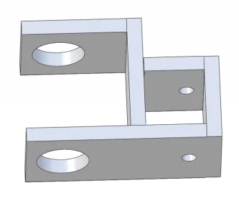
After a great discussion with @Dabbler yesterday I think I have a plan.
Involves 3" x 6" 1/2" flat stock to make the side plates and the cross brace.
I'm fortunate that John has the same machine and could see if any of the dimensions were critical to avoid interference and we determined that aside from the bearing bores there are no critical dimensions.
It will be a bolt together piece using 3/8" SHCS.
I'll CAD something up over the weekend.
Commence learning about line boring....
Last edited:
I haven't measured them but they look parallel.Are the bearing bores parallel to the pivot? I've seen instances where a shaft is canted off from the pivot for gear alignment.
It remains to be seen if I do any better 😀They probably are parallel, img0439 looks like the pivot pin hole almost missed the extra thickness in the casting and that made me wonder.
I did pick up the material today. 24" of 3" x 1/2" hot rolled was $24.
Got extra because, mis-periments 😀

