• Scam Alert. Members are reminded to NOT send money to buy anything. Don't buy things remote and have it shipped - go get it yourself, pay in person, and take your equipment with you. Scammers have burned people on this forum. Urgency, secrecy, excuses, selling for friend, newish members, FUD, are RED FLAGS. A video conference call is not adequate assurance. Face to face interactions are required. Please report suspicions to the forum admins. Stay Safe - anyone can get scammed.

DavidR8's shop shenanigans

Alright den of people much smarter than me…
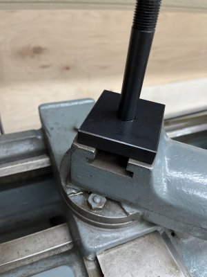
My power cross feed doesn’t work because the key for the lead screw is missing.
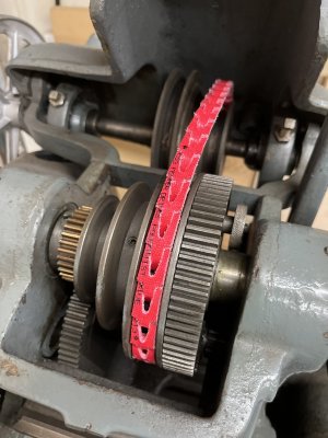
Whats more puzzling is how it’s retained in the bevel drive gear.

You can just make out a small hole at one end of the gear. So maybe a pin goes in there to retain one end.
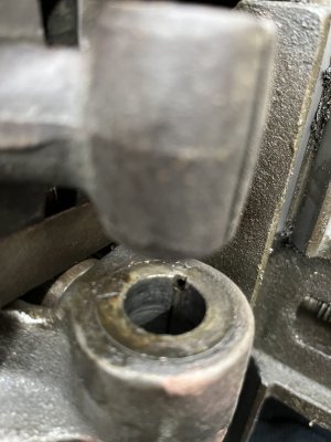
CEF70FB0-2CE7-4779-BD39-AB3C5C450D7A.jpeg
At the bevel gear end I have no idea how it’s retained.
The bevel gear end points toward the headstock so it seem to be that as soon as the carriage is moved toward the tailstock it will come out.
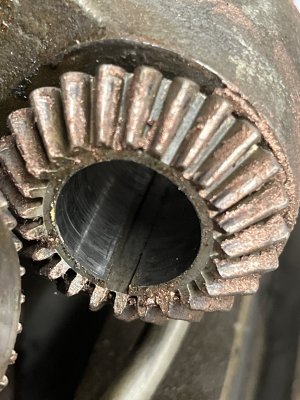
CFBC9E68-C70E-4895-85A3-A6E5985FCAE9.jpeg
Is it possible that it’s a bent key and one end goes in the hole?
 
I would try and find the little hole size using a drill index and sticking the shanks of the drill in it (gauge pins are also handy for something like this, if you have them). Also gives you an idea if the hole is drilled at and angle other than 90* to the key way axis.

Drill the hole in the key stock slightly smaller and use a roll pin (aka spring pin) of the appropriate diameter. Cut pin to length. The roll pin will be tight in the key and just a slight press into the gear. The key will never slide in the gear’s key way. It also won’t fall out once the lead screw is installed as it now is trapped in the two key ways.
Thanks, that's super helpful as I was trying to imagine how to work out the dimensions.
 
The Boston Gear catalogue which you can access on line has a page full of gear profiles that you can print out to ID your gears. It also has a table where you can look up the recommended backlash for the different gears. I used that to find the backlash for the change gears in my lathe and once you get it right the gears run a lot quieter and likely don't wear as fast.
 
The Boston Gear catalogue which you can access on line has a page full of gear profiles that you can print out to ID your gears. It also has a table where you can look up the recommended backlash for the different gears. I used that to find the backlash for the change gears in my lathe and once you get it right the gears run a lot quieter and likely don't wear as fast.
Thanks for that tip! Appreciate it :)
 
The Boston Gear catalogue which you can access on line has a page full of gear profiles that you can print out to ID your gears. It also has a table where you can look up the recommended backlash for the different gears. I used that to find the backlash for the change gears in my lathe and once you get it right the gears run a lot quieter and likely don't wear as fast.

I love it. Old guys are just awesome.

Gotta love good old fashioned 3D hand drawings like @RobinHood's and charts like yours that you can just lay a gear on to see what it is!

I also have a box of gear cutters I got with my old mill/drill. Easy as pooping in a toilet to just go through the box to find what you need.....LOL!

I like easy...... :p
 
It also has a table where you can look up the recommended backlash for the different gears. I used that to find the backlash for the change gears in my lathe and once you get it right the gears run a lot quieter and likely don't wear as fast.

OK Larry. I need some help with this. I started out trying to set backlash as per the manual for my lathe. But over the years I stopped doing it. Just plain way too much trouble.

Today I just push them all together with one hand and tighten the Banjo nut with the other. When I let go, the backlash is what it is. It's usually a tad looser than I want, but tapping the stud to fine tune it seems to be more aggressive than I am comfortable with. Maybe someday I'll make a banjo spanner. Should be lots of time for that when the grass looks white looking up.

What do you do to set backlash properly?
 
OK, here is the trick. What ever the recommended backlash is divide it by two. Then comes the hard part, you have to find some paper that is as close to exactly that thick. In my case my wife has some tracing paper for her art work that is very thin. I needed one and one half thou for my recommended 3 thou backlash. Here comes the easy part. cut a piece of the paper into a long strip the same width as the width of the gears. Put he paper between the teeth of the two gears you want to set, push them together and snug them up. Then just roll the gears over to get the paper out and your done. The reason for half the backlash is that the paper ends up on both sides of the gear teeth. pretty easy and it works well.
 
OK, here is the trick. What ever the recommended backlash is divide it by two. Then comes the hard part, you have to find some paper that is as close to exactly that thick. In my case my wife has some tracing paper for her art work that is very thin. I needed one and one half thou for my recommended 3 thou backlash. Here comes the easy part. cut a piece of the paper into a long strip the same width as the width of the gears. Put he paper between the teeth of the two gears you want to set, push them together and snug them up. Then just roll the gears over to get the paper out and your done. The reason for half the backlash is that the paper ends up on both sides of the gear teeth. pretty easy and it works well.

Sounds like a nice trick David. The question is: how do you maintain that clearance as the Banjo bolt gets tightened. If I press my gears together tightly (zero clearance) and then tighten the bolt while applying pressure, there is clearance there when I let go. So if used your method, I would get even more clearance than the paper provides when the setup relaxes as I let go.

I used to spend time with a special feeler gauge setting things up. Tighten, tap with small hammer, tighten, tap, tighten, tap, etc until everything was perfect. I gave up on that 8 years ago and just press, tighten, and cut threads. Seems to work fine but I know it isn't perfect.
I don't really have an answer for you not knowing just how your "Banjo" bolts secures the gear. All I can think is that the bolt is not square to the surface it is tightening up to which is causing the movement. You might have to inspect that closely to see if there is some way to make sure it is square to the surface before tightening.
 
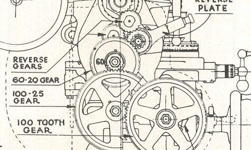
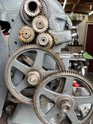
I was looking at the stack of change gears and one is a double, 60/20. Looked at the parts diagram and it belongs in the gear train.
CCD39C4E-B61E-4ACD-8DDA-4D137758AFCF.jpeg

The 60/20 should be where the left spoked 100/25 tooth gear is now
The 100/25 tooth gear needs to go on the lower arm of the banjo visible behind the gears.
I need to turn a bushing to fit over a 1/2” x 3” bolt for the 60/20 gear to run on.
B6A8C8CC-F467-4D97-A719-4B59350F2A4B.jpeg
 
Last edited:
Back
Top