• Scam Alert. Members are reminded to NOT send money to buy anything. Don't buy things remote and have it shipped - go get it yourself, pay in person, and take your equipment with you. Scammers have burned people on this forum. Urgency, secrecy, excuses, selling for friend, newish members, FUD, are RED FLAGS. A video conference call is not adequate assurance. Face to face interactions are required. Please report suspicions to the forum admins. Stay Safe - anyone can get scammed.

DavidR8's shop shenanigans

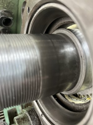
The best use of those holes is fore the drive pin when you get around to making a hand crank for your spindle, makes threading up to a thread buttress (such as barrel tenons) without worrying about "under power jam ups" a breeze
Your idea gave me the notion that if @David_R8 were to make a spider, a set screw could be positioned to seat against the hole. This would make the spider quite solid and remove any possibility of it loosening off.
 
Your idea gave me the notion that if @David_R8 were to make a spider, a set screw could be positioned to seat against the hole. This would make the spider quite solid and remove any possibility of it loosening off.
Yes that would work. The spider I built for my lathe threads inside the outboard end of the spindle so there is a shoulder to butt against and the handle drive drive hole is in the spider but Davids hole in the spindle is very usable as well.
 
I like both the spider and tach ideas. I have in proximity sensor around somewhere. Need to figure out how to make that output show up in TouchDRO.
 
I like both the spider and tach ideas. I have in proximity sensor around somewhere. Need to figure out how to make that output show up in TouchDRO.

I "believe" the touch DRO system expects a hall effect input. It would be lot easier to use a magnet and Hall effect transducer than a proximity sensor.
 
I "believe" the touch DRO system expects a hall effect input. It would be lot easier to use a magnet and Hall effect transducer than a proximity sensor.
Oh maybe that's what I have... Hmmm.... I got it as a kit with a sensor and a display. Was going to put it on my RF mill but never got to it.
 
Yup that's the one, or one just like it.
Says Hall switch so maybe I'm good?
TouchDRO's tach will take almost anything that generates a leading edge consistently. You can also scale it if you have multiple edges per revolution.
 
Yup that's the one, or one just like it.
Says Hall switch so maybe I'm good?

Technically, that's a hall effect because it has a magnet. Proximity sensors sense a passing piece of conductive metal like a gear tooth.

I guess the seller never got the memo..... LOL!

I bet @PaulL is right though. Anything that generates an edge at the right voltage level should work.
 
Technically, that's a hall effect because it has a magnet. Proximity sensors sense a passing piece of conductive metal like a gear tooth.

I guess the seller never got the memo..... LOL!
Ahh I think I actually knew that from building my CNC router. I used proximity sensors there as limit switches. No magnets required. :)
 
I am bit flummoxed by how the spindle is supposed to go back together.
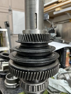
The order of the parts: bull gear, spindle pulley, locking collar, sliding gear for feed direction and a spacer.
There are keys under the bull gear and the sliding gear.
Problem is that with all the seals in place I can't get the key for the sliding gear in place because of the the combined width of all the components is exactly the width of the space in the headstock.

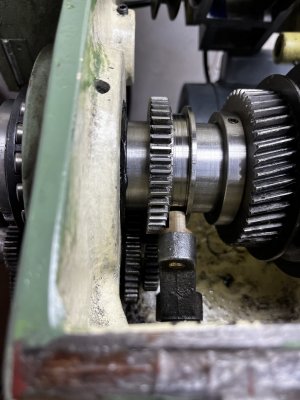
This is everything up to where the key for the sliding gear goes.
IMG_0706.jpeg
The only thing I can think to do is pull the inside seal at the outboard side.
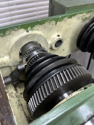
So I pulled the seal. Presto I can get everything in place including the keys.
IMG_0708.jpeg

The space between the bull gear and the headstock is where the locking pin rotates. In this pic, the bull gear is hard up against a shoulder on the spindle.
IMG_0709.jpeg
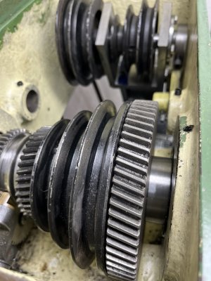
Problem is that when I shift the forward/reverse lever to engage the gears the last spacer intrudes into the space where the seal goes.
IMG_0710.jpeg
 
Last edited:
Does the gear mesh with the reverse gears okay? Is the gear bored for the spacer to fit inside the gear?

Is it an illusion or is the counter pulley in need of a 180?
The gears mesh perfectly if the spacer is in the space where the seal goes. Otherwise it only engages forward and neutral.
And yes I have the counter pulley on the wrong direction :rolleyes:
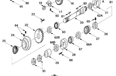
I'm taking another look at the parts diagram because I must have it screwed up somehow.

Edit: I do have it in the wrong order.
The sliding gear (p/n 27) goes on, then the whole thing slides through the seal (which I see now that I could have left in place) the bearing (p/n 67) then the retaining ring (p/n 28) then the spacer and then the lock nuts.
Ok I feel dumb now.
 

Attachments

  • Screenshot 2023-11-09 at 14-14-33 g1003_m - g1003_m.pdf.webp
    Screenshot 2023-11-09 at 14-14-33 g1003_m - g1003_m.pdf.webp
    38.4 KB · Views: 5
Last edited:
Back
Top