Or if you really want strength, SHCS ( socket head cap screws). But carbide inserts please!!Homedepot 1/2" x 6" hex head grade 8 bolt should do the trick. About $7. Grade 5= $5.15
-
Scam Alert. Members are reminded to NOT send money to buy anything. Don't buy things remote and have it shipped - go get it yourself, pay in person, and take your equipment with you. Scammers have burned people on this forum. Urgency, secrecy, excuses, selling for friend, newish members, FUD, are RED FLAGS. A video conference call is not adequate assurance. Face to face interactions are required. Please report suspicions to the forum admins. Stay Safe - anyone can get scammed.
-
Several Regions have held meetups already, but others are being planned or are evaluating the interest. The Calgary Area Meetup is set for Saturday July 12th at 10am. The signup thread is here! Arbutus has also explored interest in a Fraser Valley meetup but it seems members either missed his thread or had other plans. Let him know if you are interested in a meetup later in the year by posting here! Slowpoke is trying to pull together an Ottawa area meetup later this summer. No date has been selected yet, so let him know if you are interested here! We are not aware of any other meetups being planned this year. If you are interested in doing something in your area, let everyone know and make it happen! Meetups are a great way to make new machining friends and get hands on help in your area. Don’t be shy, sign up and come, or plan your own meetup!
You are using an out of date browser. It may not display this or other websites correctly.
You should upgrade or use an alternative browser.
You should upgrade or use an alternative browser.
D. Gray D&D - HEAVY DUTY KNURLING TOOL KIT
- Thread starter YYCHM
- Start date
Worked on the tension knob today....

After a whole bunch of mucking round (truing, drilling, tapping, thread a mandrel to hold it) I finally got to the point of knurling it. It's not as crooked as the image depicts LOL.

Then I discovered the body tang is too wide for my tool holders, so it was off to the mill for a trim....

Finally got to point of knurling only to discover.... The whole tool is too long for my lathe @#@$%^#%%#&&((
After a whole bunch of mucking round (truing, drilling, tapping, thread a mandrel to hold it) I finally got to the point of knurling it. It's not as crooked as the image depicts LOL.
Then I discovered the body tang is too wide for my tool holders, so it was off to the mill for a trim....
Finally got to point of knurling only to discover.... The whole tool is too long for my lathe @#@$%^#%%#&&((
VicHobbyGuy
Ultra Member
Very unsatisfactory! Can Gray provide replacement plates or can you shorten the tool somehow? Can you fit the knurler into a lantern toolpost?
Is that as far back as the cross slide will go (I'm sure it is but had to ask :-(
Yes
Homedepot 1/2" x 6" hex head grade 8 bolt should do the trick. About $7. Grade 5= $5.15
Grade 5 is more than adequate and easy to machine. Bolts are cheap. That is what I would do too.
For the threads, I'm not sure how ppl can determine that your overall diameter is wrong from a photo, a skill I don't have yet.
Bear with me on this one @gerritv. It might be a rough ride.
This result is from geometry, not from looking at a photo.
In order for the nut to actually thread on, the thread root must be close to full depth. Perhaps a little less due to tolerances.
If the advancing tool follows a 60 degree slope (because of the compound setting) while cutting the thread, it takes a longer path to reach full thread depth. And therefore the trailing slope of each thread is also longer than it should be.
However, the advancing side of the cut is dictated by a form tool cut at the standard 30 degrees not by the compound angle. When the 60 degree cut reaches full depth (to allow the nut to go on) the 30 degree form cut removes about 1/4 of the top of the thread ahead of it. This reduces the diameter of the threaded shaft by about a quarter of the thread depth.
The overall effect should be a fairly clean leading edge on the thread from the form tool and a pretty ragged trailing edge from the combined form and compound angle.
My concern is that the nut will feel ok because the tip of the thread on the nut will engage and follow the root. But the nut will have no support on the 60 degree angle at all and the effective thread engagement will also be reduced by the smaller diameter. All in all, not a good outcome for something that sees very high tensile loads.
Feel free to challenge and/or ask questions. I take no offense especially since this is clearly not intuitive.
Too bad I don't have @PeterT's drawing skills!
Oh no, you must be super dissapointed. All that work and it doesn’t fit.Finally got to point of knurling only to discover.... The whole tool is too long for my lathe @#@$%^#%%#&&((
Hope you’re able to find a solution.
gerritv
Gerrit
I understand the drawings and likely what happened given the compound setting. It's interesting though in that the nut will act on the other side of the V (rh side) as it is tightened, the rod is being pulled, not pushed.
I am just saying that without measuring the actual thread result you can't tell from a photo. It could be that the incorrectly ground angle compensates and the end result is 'close enough'. Craig could have cut deeper and 'made up for it'. Also don't know what the tip of the tool really looks like. I can't tell from the photos.")
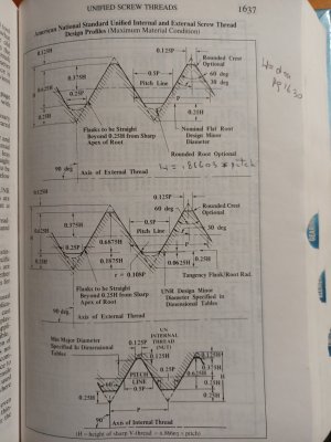
Actual full thread depth is .625 * pitch regardless of UN/UNC/UNF or even metric. Also known as major diameter-minor diameter. The theorectical point to point is .8663 * pitch but those tips are always/should be lopped off. All predicated on starting with the correct diameter work piece, which for 5/16-24 would likely be .3114, not .3125. This stuff is engrained in a (slowing) brain due to struggling matching threads internal and external on some old stuff. It was supposed to be BA but had 55dg angle And other peculiarities. In the end had to grind internal and external custom tooling.
I am just saying that without measuring the actual thread result you can't tell from a photo. It could be that the incorrectly ground angle compensates and the end result is 'close enough'. Craig could have cut deeper and 'made up for it'. Also don't know what the tip of the tool really looks like. I can't tell from the photos.
Actual full thread depth is .625 * pitch regardless of UN/UNC/UNF or even metric. Also known as major diameter-minor diameter. The theorectical point to point is .8663 * pitch but those tips are always/should be lopped off. All predicated on starting with the correct diameter work piece, which for 5/16-24 would likely be .3114, not .3125. This stuff is engrained in a (slowing) brain due to struggling matching threads internal and external on some old stuff. It was supposed to be BA but had 55dg angle
And other peculiarities. In the end had to grind internal and external custom tooling.Attachments
Not one to give up.........

I lobbed off the back fillets on the body plate with the mill. That bought me just enough room to move the tool back in the tool holder.

This is the tension knob knurled. The tool created a nice crisp bold knurl in brass. I discovered that you can torque down the knurling wheels to point of spinning the mandrel in the chuck

Tool installed in a tool holder with tension knob install I think the real solution here is to shorten a tool holder 3/8" or 1/2" or so.
I lobbed off the back fillets on the body plate with the mill. That bought me just enough room to move the tool back in the tool holder.
This is the tension knob knurled. The tool created a nice crisp bold knurl in brass. I discovered that you can torque down the knurling wheels to point of spinning the mandrel in the chuck
Tool installed in a tool holder with tension knob install
I think the real solution here is to shorten a tool holder 3/8" or 1/2" or so.
Last edited:
D. Gray Drafting & Design
Member
That's great news Craig. I was just about to PM you about some replacement plates. Now everything you see will need a knurl.
Nice save!!Not one to give up.........
View attachment 25861
I lobbed off the back fillets on the body plate on the mill. That bought me just enough room to move the tool back in the tool holder.
View attachment 25862
This is the tension knob knurled. The tool created a nice crisp bold knurl in brass. I discovered that you can torque down the knurling wheels to point of spinning the mandrel in the chuck
View attachment 25863
Tool installed in a tool holder with tension knob install
That's great news Craig. I was just about to PM you about some replacement plates. Now everything you see will need a knurl.
Interesting.... Do you have shorter arm plates?
you're like a leech with lock jaw, nothing can make you let go of the goal
LOL... Badger maybe, Leech no. Wife calls it being Tenacious.
I understand the drawings and likely what happened given the compound setting. It's interesting though in that the nut will act on the other side of the V (rh side) as it is tightened, the rod is being pulled, not pushed.
I am just saying that without measuring the actual thread result you can't tell from a photo. It could be that the incorrectly ground angle compensates and the end result is 'close enough'. Craig could have cut deeper and 'made up for it'. Also don't know what the tip of the tool really looks like. I can't tell from the photos.
Actual full thread depth is .625 * pitch regardless of UN/UNC/UNF or even metric. Also known as major diameter-minor diameter. The theorectical point to point is .8663 * pitch but those tips are always/should be lopped off. All predicated on starting with the correct diameter work piece, which for 5/16-24 would likely be .3114, not .3125. This stuff is engrained in a (slowing) brain due to struggling matching threads internal and external on some old stuff. It was supposed to be BA but had 55dg angle
I'm thrilled that you were able to follow what I was describing.
And yes, I agree that for this instance and the way the rod was held and fits the assembly, the nut will bear on the better left 30 degree slope.
But as per my first note, my real concern is the reduced effective diameter.
Looks like Craig (@YYCHM) was able to slip the part being knurled in the chuck though, so perhaps it's still plenty enough. And he does plan to make a proper tensioner bolt down the road so I'm just gunna drop it for now. If he ever strips the rod in future, we will know why.
Interesting.... Do you have shorter arm plates?
And another tentioning rod.....
And another tentioning rod.....
Well if your going to go that far.... and another hinge pin as well LOL.
This result is from geometry, not from looking at a photo.
In order for the nut to actually thread on, the thread root must be close to full depth. Perhaps a little less due to tolerances.
If the advancing tool follows a 60 degree slope (because of the compound setting) while cutting the thread, it takes a longer path to reach full thread depth. And therefore the trailing slope of each thread is also longer than it should be.
However, the advancing side of the cut is dictated by a form tool cut at the standard 30 degrees not by the compound angle. When the 60 degree cut reaches full depth (to allow the nut to go on) the 30 degree form cut removes about 1/4 of the top of the thread ahead of it. This reduces the diameter of the threaded shaft by about a quarter of the thread depth.
The overall effect should be a fairly clean leading edge on the thread from the form tool and a pretty ragged trailing edge from the combined form and compound angle.
I agree. That's what we are looking at - the telltale thread form, not the diameter.
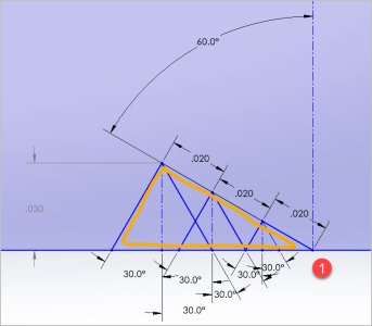
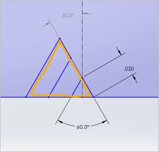
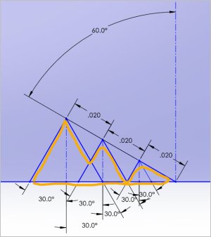
I had to think about this a bit sketch wise. Not sure I have it right but here goes. First pic shows the compound set at 30-deg. I advanced the 60-deg tool in 3 equal increments of (arbitrary) 0.020". Orange shows the net result, a typical 60-deg V thread to full depth. Second pic shows compound set at oops 60 deg & infeeding same equal compound advancement. Result is raggedy trailing edge as @Susquatch says and OK looking leading edge. The actual sawtooth shape will be dictated by whatever sequence of infeeds actually occurred. The other telltale sign should have been the cookbook DOC should result in a shallower male thread pitch diameter & should not have fit. That's why when I saw the nut threaded on I was a bit mystified. Maybe you kept going till it went on? (And yes, I have made this exact mistake myself.)
Attachments
@gerritv , @Susquatch the major dia of the tension rod ended up being 0.303" if that sheds some light on the situation.
Last edited:
Hmmm, maybe I have this wrong. If after each DOC thread pass, the tool is retracted out by cross slide, return to start of thread, zeroed to same position (1) then infeed next DOC increment with compound only, then the trailing edge should be the wrong (shallow) angle but more reasonably smooth, not sawtoothy like I drew before.