-
Scam Alert. Members are reminded to NOT send money to buy anything. Don't buy things remote and have it shipped - go get it yourself, pay in person, and take your equipment with you. Scammers have burned people on this forum. Urgency, secrecy, excuses, selling for friend, newish members, FUD, are RED FLAGS. A video conference call is not adequate assurance. Face to face interactions are required. Please report suspicions to the forum admins. Stay Safe - anyone can get scammed.
-
Several Regions have held meetups already, but others are being planned or are evaluating the interest. The Calgary Area Meetup is set for Saturday July 12th at 10am. The signup thread is here! Arbutus has also explored interest in a Fraser Valley meetup but it seems members either missed his thread or had other plans. Let him know if you are interested in a meetup later in the year by posting here! Slowpoke is trying to pull together an Ottawa area meetup later this summer. No date has been selected yet, so let him know if you are interested here! We are not aware of any other meetups being planned this year. If you are interested in doing something in your area, let everyone know and make it happen! Meetups are a great way to make new machining friends and get hands on help in your area. Don’t be shy, sign up and come, or plan your own meetup!
You are using an out of date browser. It may not display this or other websites correctly.
You should upgrade or use an alternative browser.
You should upgrade or use an alternative browser.
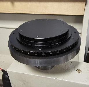
Compound needs a better degree dial
- Thread starter Susquatch
- Start date
Simpler method? It’s aluminum. It has tapped mounting holes. Bolt it to a faceplate, center it. Trepan to <almost> cut through. Unbolt. Drill through the remaining web. Grab a coping saw and cut out the web. File to fit.
I like it! This has promise and if it works, it would save me from having to make a huge collet!
Everyone is talking lathe, what about on the milling machine.
-hole saw or trepanning tool
-boring head
or rotary table
Clamp a sacrificial disc on top of your dial, like a sandwich. Or use crazy glue.
This way no marring of the numbered edge of the dial.
-hole saw or trepanning tool
-boring head
or rotary table
Clamp a sacrificial disc on top of your dial, like a sandwich. Or use crazy glue.
This way no marring of the numbered edge of the dial.
historicalarms
Ultra Member
I would use a 4-jaw and center the piece perfectly in the jaws ( using light grip force and then glue to the chuck face with best glue i could find. Wife claims that "gorilla glue" the best that she has ever used.
Now re-clamp the 4 jaws to lightly hold and help alleviate the torsion of the cutting force on the glue
Now re-clamp the 4 jaws to lightly hold and help alleviate the torsion of the cutting force on the glue
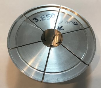
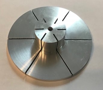
I made this specifically to trepan a thin part.
This is more or less the same as my thoughts but your design has a few improvements I like.
I am a fan of custom collets. I make them all the time. So it's quite natural for me to head down that path with this problem. I was gunna shoot for the same 1 thou fit but with only one slit. I reasoned that a really close fit didn't require distributed compression. Positioning the one slot halfway between two of the jaws would permit me to index the collet to ensure a perfect non-elliptical center in the degree ring. But I think three jaws isnt hard to do and would guarantee that outcome. It solves another problem I've been noodling too - how to bore the degree ring when it is sitting flat against the check jaws. I was going to make another ring for that purpose alone, but a collet like yours could have that feature integrated right into the collet itself.
A few other points for discussion.
1. Is it better to have the collet ears articulate about a central hub, or is it better to make the backplate solid but very thin at the outside inner corner and have the plate articulate like three ears around an inner outside rotation point - like bending just your finger tips but not your fingers to hold the degree collar. I wish I had modelling capabilities to evaluate this, but the old fashioned build and test works too.
2. The degree ring needs to be adjustable to calibrate it to my compound travel. Should the degree ring be a perfect fit to the plynth or should it have 3 or 6 points of contact that are deformed for installation and then released to hold or should I just use a few tiny grub screws?
I am gunna noodle all this for a while. But I need some plate anyway to make an indicator base for my lathe (yet another great lathe improvement project @Dabbler suggested). So I think I'll get a stock order in process right away.
New fresh ideas or improvements or even just discussion are still always welcome.
then glue to the chuck face with best glue i could find
This would work but has a problem for this application.
It doesn't provide a relief to cut the ring bore without also cutting the chuck face.
However, I like the idea of using the Jaws as backup for the glue.
I guess I should also confess a slight aversion to glue. The degree ring is anodized on the outside, front, and rear. I don't want to damage those surfaces if I can avoid it. So any glue I use must be easily and completely removed without damaging the anodized surface of the collar.
it could be mounted the same way on a metal plate mounted in a 4jaw.
Unless I misunderstand you, that's my preferred approach till I hear or think of something better.
I have no fear of centering on a four jaw or a table. I have 40 plus years of getting that process down to an instinctive habit.
Not directly related to topic but just so happen to have an angle block in the mill & took a picture to show a method to obtain or check an angle. DRO makes it very quick & easy. I have an indicator in the quill, touch down to register a value, say zero. Now null DRO X & Z to zero, retract quill. Move the table over to the other end of the block, any length will do. Touch DTI to same zero again, record new X & Z DRO values at that position. Angle = ArcTan(Y/X). Here I'm checking an offshore angle block (they're not that great actually) but it could just easily be a part to be machined, although fussier to set up to a target angle unless you can pivot on one corner. The same general principle can be used in a lathe on a cylindrical bar.
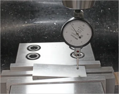

I have an indicator in the quill, touch down to register a value, say zero.
Since lots of guys don't have Z-Axis DRO, it is worth pointing out that your method only works if you use the same zero on the indicator. However, you can do the same thing with a plunge indicator instead of a dial test indicator and then use your X-Axis DRO and the plunge indicator readings to calculate the angle instead.
Those without any DRO at all can also use the table dials with a plunge indicator if they remember to take up the backlash in the same direction for both measurements.
a smile
Lifelong hobby - cold iron
Very determined!哈哈!擦进去。
当我还能呼吸并发誓时,CNC永远不会碰我的车床。
Very old school!
I think, this is the right persistence!
But being as electronic as possible still makes it easier to use.
Last edited:
I want to know in what state do I use Angle apps that exceed +/ -60?
The translation isn't excellent but I think I know what you want to know.
29.5 degree threading is usually set as 60.5 on a compound.
Negative compound travels are always beyond 60. This is where the compound is rotated such that the crank is at the back of the lathe and the tool travels toward or away from the user.
For very large parts. Say you have a 12" lathe and an 11.5" disk but you need to work on the circumference or the back side. It isn't possible to do that without rotating the crank so it is at the rear of the cross-slide.
Just a few I've had to do.
Time to work on my 360 degree dial for my compound.
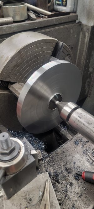
I threaded the plate for a fine thread 1.5" stub arbour. Then had at it.
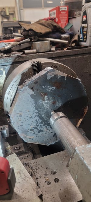
Took almost 2 days to trepan this 1/2" plate to make the collet to hold the dial. I could only cut a thou at a crack cuz the thing chattered like an old lady! My autofeed doesn't go that shallow so I had to feed it manually just skirting the chatter.
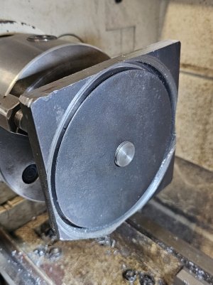
I know, I should have just torched the ears off.
Here it is ready for turning.
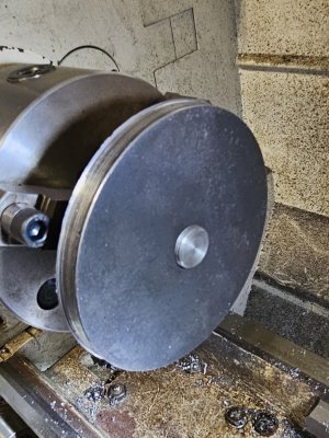
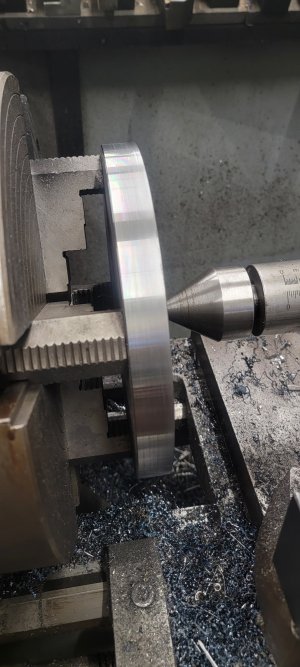
And here it is turned down with just enough to make collet ears to hold the degree disk.
Next, I'll remove most of the center, with flats to hold the degree disk concentric and flat, and then cut 8 slits in the disk to make flexible collet ears. Each jaw of my 4 jaw chuck will close two collet ears onto the degree disk. I might test it with 4 collet ears each centered on a jaw first.
I threaded the plate for a fine thread 1.5" stub arbour. Then had at it.
Took almost 2 days to trepan this 1/2" plate to make the collet to hold the dial. I could only cut a thou at a crack cuz the thing chattered like an old lady! My autofeed doesn't go that shallow so I had to feed it manually just skirting the chatter.

I know, I should have just torched the ears off.
Here it is ready for turning.

And here it is turned down with just enough to make collet ears to hold the degree disk.

Next, I'll remove most of the center, with flats to hold the degree disk concentric and flat, and then cut 8 slits in the disk to make flexible collet ears. Each jaw of my 4 jaw chuck will close two collet ears onto the degree disk. I might test it with 4 collet ears each centered on a jaw first.
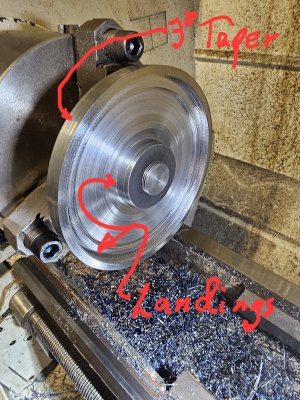
Got a bit more done last night.
The outside rim of the collet is tapered so the chuck jaws will cause the collet to close as the Jaws tighten.
The part will sit mainly on the outer landing so it sits flat. It should sit on the inner landing too until the collet is closed. I'll take the whole arbour down to the landing height as I get close, but need it for rigidity for now.
Lots of chatter because the part is thin. I'll switch to a hand sharpened HSS tool to clean up the chatter at the same time as I close in on final dimensions.
@Darren's approach would have much less chatter by design. Mine is a bell that likes to sing.

I did the same thing last night except I torched it, and pressure turned it against the chuck jaws. No chatter or singing this way.
What are you making Darren?

