Yes, its very possible. Just very time consuming. I made these for my Standard Modern. I did not cut the teeth though. I made everything else and took them to a company that cut the teeth, (which of course I don't remember now since it was 20 years ago.)Is it possible to make a few gears to provide metric threading capability?
I didn't say practical, I just want to start with possible and go from there.
I'm planning to turn a metric part tomorrow afternoon. I'll have a closer look at my lathe to see what that might take.
-
Scam Alert. Members are reminded to NOT send money to buy anything. Don't buy things remote and have it shipped - go get it yourself, pay in person, and take your equipment with you. Scammers have burned people on this forum. Urgency, secrecy, excuses, selling for friend, newish members, FUD, are RED FLAGS. A video conference call is not adequate assurance. Face to face interactions are required. Please report suspicions to the forum admins. Stay Safe - anyone can get scammed.
-
Several Regions have held meetups already, but others are being planned or are evaluating the interest. The Calgary Area Meetup is set for Saturday July 12th at 10am. The signup thread is here! Arbutus has also explored interest in a Fraser Valley meetup but it seems members either missed his thread or had other plans. Let him know if you are interested in a meetup later in the year by posting here! Slowpoke is trying to pull together an Ottawa area meetup later this summer. No date has been selected yet, so let him know if you are interested here! We are not aware of any other meetups being planned this year. If you are interested in doing something in your area, let everyone know and make it happen! Meetups are a great way to make new machining friends and get hands on help in your area. Don’t be shy, sign up and come, or plan your own meetup!
You are using an out of date browser. It may not display this or other websites correctly.
You should upgrade or use an alternative browser.
You should upgrade or use an alternative browser.
AXA Tool Holder(s)
- Thread starter YYCHM
- Start date
I'm actually not sure what the advantage of dog point is myself, maybe someone can illuminate.
Didn't see a response. The smaller OD of the dog point on the screw reduces the tendency of the screw to push the part aside as you tighten down the screw. That's also why I tighten the screws in sequence just a little at a time. I don't want a gap to develop in there. Ideally, you would want an actual point on the screw and a matching recess on the tool, but that creates a different bigger set of problems to deal with.
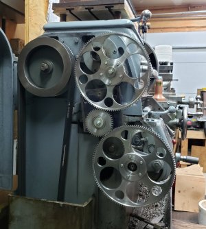
Yes, its very possible. Just very time consuming. I made these for my Standard Modern. I did not cut the teeth though. I made everything else and took them to a company that cut the teeth, (which of course I don't remember now since it was 20 years ago.)
Those look a lot bigger than needed. I'm assuming you went a lot higher than 100/127 to do this. But ya, that's the idea.
I'll be in the shop cutting that metric thread later today. I'm planning to take a closer look at how my lathe gears are setup to be able to provide some food for thought on the matter.
They're actually 127 and 120. When I made them, I thought I should use the same size/type teeth as the rest. In retrospect, I could have made them smaller, but then I would need a larger idler gear(s) to connect the two. I was going to make the 125 and 140 gear as well, but the 120 gave me all the metric thread pitches I required.Those look a lot bigger than needed. I'm assuming you went a lot higher than 100/127 to do this. But ya, that's the idea.
I'll be in the shop cutting that metric thread later today. I'm planning to take a closer look at how my lathe gears are setup to be able to provide some food for thought on the matter.
Attachments
trlvn
Ultra Member
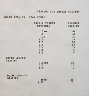
Sometimes it is possible to turn threads that are 'close enough'. My ancient Atlas 618 is capable of producing threads that closely approximate standard metric sizes using only the original change gears. See page 4 of the attached.My lathe doesn't turn metric threads.
A typical nut only engages maybe 5 to 10 threads. Even if the thread is a little off, it won't be enough to prevent the nut from turning. OTOH, if you must have a LOT of threads engaged, the approximate threads won't work.
FWIW,
Craig
Attachments
RobinHood
Ultra Member
Very nicely done Sir!They're actually 127 and 120. When I made them, I thought I should use the same size/type teeth as the rest. In retrospect, I could have made them smaller, but then I would need a larger idler gear(s) to connect the two. I was going to make the 125 and 140 gear as well, but the 120 gave me all the metric thread pitches I required.
Your method has the advantage that you only need 3 gears (2, if you can use an existing idler).
SM solved the large gear problem by changing the DP of the off-units gears to 24 (IIRC) and compounding them. It allowed for the cover to close and the thru hole in the spindle to be used (this is essential when using a collet closer). You do need at least one mating gear of the same DP with the 127T transposing gear - these can get (and do get) lost over the life of the lathe.
So that is a drawback of their method. I doubt that anyone would lose the gears you made… they are just too nice.
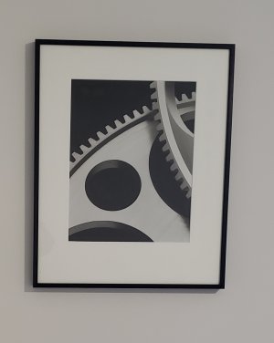
Thank you Robin. I had my dad cut the holes on the milling machine with hole saws. Literally hours of mindless work, but he was eager to help. Pulling down on the quill, applying cutting oil, blowing out the chips with air. After each hole, I would rotate the gear to the proper location and he would start again. I couldn't use the existing idlers, so I made up that one in the photo attached to a steel plate which was able to pivot so that the two big gears could mesh. The gears turned out so well visually, I photographed them, and the photo is up on the wall. An abstract!Very nicely done Sir!
Your method has the advantage that you only need 3 gears (2, if you can use an existing idler).
SM solved the large gear problem by changing the DP of the off-units gears to 24 (IIRC) and compounding them. It allowed for the cover to close and the thru hole in the spindle to be used (this is essential when using a collet closer). You do need at least one mating gear of the same DP with the 127T transposing gear - these can get (and do get) lost over the life of the lathe.
So that is a drawback of their method. I doubt that anyone would lose the gears you made… they are just too nice.
Attachments
Sometimes it is possible to turn threads that are 'close enough'. My ancient Atlas 618 is capable of producing threads that closely approximate standard metric sizes using only the original change gears. See page 4 of the attached.
This matter was the subject of a huge debate and eventually a formal study at the company before I retired. We actually paid to have a global expert flown in from England to help assess the research.
The answer we got was "it depends". LOL!
Yes, the length of thread engagement was an important factor, but so was the load, the material, lubricant, and the application. The trickiest part of the fastener debate lies in the way that the male and female threads intentionally stretch, compress, and deform under load. To be properly torqued they MUST BE deformed. Proper deformation is inherent in the design and the intent of a threaded connection. Normally a fastener does not stretch evenly. Rather, the load is taken up elasticly from the first to the last threads according to the distortion caused by the load with the highest load at the closest thread and the lowest at the furthest.
The problem with a close mix of metric and imperial threads is that this design load distribution is disrupted by the slight difference between the thread pitch for the two types.
Thus mixed threads - even those very close to being the same - cannot carry the same loads as matched threads can.
In this particular case, none of this matters because the height adjustment stud on a tool holder carries virtually no load.
But still, I thought it worth sharing the knowledge.
DPittman
Ultra Member
Hmmn I could of told your company that for alot less than what it cost to fly in a global expert.Thus mixed threads - even those very close to being the same - cannot carry the same loads as matched threads can.
Hmmn I could of told your company that for alot less than what it cost to fly in a global expert.
Ya, you could have. And so did our own studies. But when millions are on the line a second opinion from a global expert was appropriate.
And much as this might suck to say and hear, we all need to understand that trust is earned, not given.
Lots of advice I could give to the world that would be spot on. Nobody would listen. It was ever thus.
Brent H
Ultra Member
@Susquatch : you could have just retired, returned as a consultant with your own insurance and company trust would have been there for you - LOL
@thestelster : those are some pretty gears!!! Lathe is sporting some bling for sure!
@thestelster : those are some pretty gears!!! Lathe is sporting some bling for sure!
you could have just retired, returned as a consultant with your own insurance and company trust would have been there for you - LOL
A lot of guys did just that. But the corporation I worked for had a policy against it. Too many guys setup their own retirement consulting golden parachutes. So when I retired I had to sign an an agreement to never come back plus a non compete for 5 years.
No issues w me. I did a fair bit of consulting that met the terms of my retirement before deciding to take up farming full time instead. I'm much happier watching corn grow, spinning the wheel of a tractor or a lathe or a mill. Besides, I hated travel and I never did like writing reports.
Ya, I love those gears. And the wall photo of them too!
It keeps the two nuts from sticking together, whether that is the real purpose or not, but that's about all I have noticed different between mine and China's toolholders....
@140mower & @YYCHM
I think there might be a wee bit more to it than that. I think it could also provide some adjustability. The whole purpose of the knurled nut is to be able to adjust the tool height. If you have to "firmly lock" the two nuts together, it gets hard to make fine tune adjustments. But if the two nuts are held apart by a wavy washer that is only tightened by hand, it's easy to fine tune the adjustment in a way that can be adjusted but does not move afterward. The whole thing is only a locator that takes no load.
I'm not at all sure of that though. It's just a speculative opinion.
Question - Are the aluminum holders worth finishing or will they just give me grief down the road?
Did you try this? Did it work?
Maybe for light duty but why bother unless its just prototyping for the real ones. Guessing 6061 aluminum but anyways certainly won't be as strong as steel for this application. Not just the dovetail but the toolholder slot set screws.
So, I want to make a custom tool holder to hold a spindle motor in my tool post. The motor came with an alumnium clamp holder.
My first thought was to machine one side of it flat and drill and tap a steel tool holder to hold the Aluminium holder. But it seems like there are lots of reasons why that wouldn't work as well as it seems it should.
So I'm rethinking this now. Reading this thread has me thinking it would be better to make a new sleeve that incorporates its own tool holder dovetail to attach directly to the tool post dovetail.
Hence my questions about how well your aluminum tool holder worked out.
I'll also need to find a big ars chunk of aluminum that is hiding my holder inside it.
I need to be able to cut good dovetails too.....
DPittman
Ultra Member
Why not use a ready made holder and mount a bar to your motor sleeve that would fit into the tool holder?Did you try this? Did it work?
So, I want to make a custom tool holder to hold a spindle motor in my tool post. The motor came with an alumnium clamp holder.
View attachment 20594
My first thought was to machine one side of it flat and drill and tap a steel tool holder to hold the Aluminium holder. But it seems like there are lots of reasons why that wouldn't work as well as it seems it should.
So I'm rethinking this now. Reading this thread has me thinking it would be better to make a new sleeve that incorporates its own tool holder dovetail to attach directly to the tool post dovetail.
Hence my questions about how well your aluminum tool holder worked out.
I'll also need to find a big ars chunk of aluminum that is hiding my holder inside it.
I need to be able to cut good dovetails too.....
Hence my questions about how well your aluminum tool holder worked out.
I'll also need to find a big ars chunk of aluminum that is hiding my holder inside it.
I need to be able to cut good dovetails too.....
I don't know how well the aluminum holders work yet, I'm waiting on set screws to finish them. I'm going to finish the un-shimmed aluminum and steel holder and sit on the other two aluminum holders incase I get inspired to make some sort of instrumentation holder out of them.
I've been looking at this https://www.amazon.ca/gp/product/B01C8NFZJC/ref=ox_sc_saved_title_1?smid=A1CYSEWV5K86KD&psc=1 recently. The shaper while fun is just a little too time consuming and difficult to setup.
What do all the sides of that spindle motor clamp look like?
Last edited:
DPittman
Ultra Member
Yes I think one would make a great dial indicator holder for the tool post. If you haven't already seen it, Tubalcain has a video where he made just that.I get inspired to make some sort of instrumentation holder out of them.
Why not use a ready made holder and mount a bar to your motor sleeve that would fit into the tool holder?
Exactly what I was thinking as well.
Yes I think one would make a great dial indicator holder for the tool post. If you haven't already seen it, Tubalcain has a video where he made just that.
I did that myself with a regular steel tool holder. I didn't see it anyplace else, it just seemed infinitely better than mounting it into my tailstock....
It works great for dialing in a bore.
When I go out to the shop I'll take a photo of that as well as the spindle motor bracket.