• Spring 2024 meetup in Calgary - tentative date Saturday, April 20/2024. Other regions are also discussing meet ups. If you want one in your area get going on organizing it! discussion
  • We are having email/registration problems again. Diagnosis is underway. New users sorry if you are having trouble getting registered. We are exploring different options to get registered. Contact the forum via another member or on facebook if you're stuck. Update -> we think it is fixed. Let us know if not.
  • Spring meet up in Ontario, April 6/2024. NEW LOCATION See Post #31 Discussion NEW LOCATION

Anyone own a GH1440W lathe from Modern Tools or a PM1440HD from Precision Matthews?

John Conroy

member
Premium Member
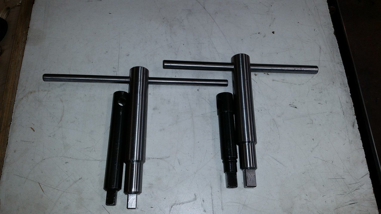
I've noticed that the headstock on this lathe is taller from the centerline of the chuck to the top of the lid and adding the tool tray had made it taller still. The consequence of that is the chuck keys are too short so the T handles interfere with the tray. I have quite a bit of 1" cold rolled so I made up 2 new handles. Of course the 3 jaw and 4 jaw chucks take different sizes:confused:. I was able to improve the fit of the square end of the keys over the originals also.
20190322_105811.jpg
 

PeterT

Ultra Member
Premium Member
Nice.
I have the same issue on one of my keys. Its on the to-do list. One feature I have come to like is the tommy bar has a slide fit so you can slide it to one side. Not so much for gronking but gives you a bit of leverage and its off to one side instead of interfering with the headstock if the nuts aren't quite upright. The commercial tommy bar has these rubber end caps to retain it. You could either use your new ball maker for the classic look. Or one simple trick I did on a similar handle is to machine a groove depression out near the end & install an O-ring so it stands slightly proud. Its very resilient & has a nice dampening effect if the bar slides down.
 

Dabbler

ersatz engineer
Certainly the way to go. One of the Youtubers made a special 'front Key' for doing 4 jaw work - it was around 10" reach... On my old lathe, the 3&4 jaw chucks had different sized keys. My new one uses the same key - go figure!
 

John Conroy

member
Premium Member
As I mentioned previously, I'm not too happy with the piston style quick change tool post that came with the machine. I ordered a wedge style from All Industrial Tool on eBay. I chose this one as it looks very much like the one I had on my old lathe and the shipping was reasonable. It arrived yesterday and it looks pretty good. It uses Imperial threads (5/8" X 18 on the post) like my old one did and the machining is pretty nice. I had to mill the base to fit my compound and at the same time I disassembled the compound and cleaned and inspected it then drilled and tapped two m5 holes for set screws to hold the base from sliding in the compound.

The machine work on the compound is very nice. The more I use this new machine the more impressed I am with it. 20190327_191922.jpg 20190327_161014.jpg 20190327_161025.jpg 20190327_155608.jpg 20190327_160310.jpg 20190327_161102.jpg 20190322_114500.jpg 20190322_114452.jpg 20190322_113825.jpg
 

PeterT

Ultra Member
Premium Member
Good job.
Are there T-nuts to secure the compound after swivelling to new position kind of like your Cantek lathe or something better?
 

John Conroy

member
Premium Member
It has T bolts instead of nuts. I think they work better, they don't seem to get caught when rotating the compound.
 

John Conroy

member
Premium Member
I don't like the bed mounted carriage stop so I made up an improved version of the one I made for my old lathe, which is a copy of a Hardinge design. In the last pic you can see that the old carriage stop prevents the carriage from moving close to the headstock. The new one is much easier to use and is always mounted.

20190414_113925.jpg 20190414_113910.jpg 20190414_114037.jpg 20190414_114123.jpg 20190414_114156.jpg 20190414_115258.jpg
 

John Conroy

member
Premium Member
The threads on the thimble are 7/16" 20 tpi so each revolution gives .050" of adjustment. I machined 10 grooves around the circumference of the thimble end, each long groove indicates .010" and the short ones are .005" increments. 20190427_120038.jpg 20190427_120047.jpg 20190427_120121.jpg
 

ducdon

Super User
Premium Member
I have the C0636A 14-40 from Modern Tool that I bought about 15 years ago. I have no complaints with the quality, but the gearbox does not cover a very wide range of speed and feeds nor thread pitches without changing the gear train. Might be something you would want to check?
 

John Conroy

member
Premium Member
I machined a spider for the left end of the spindle. It has 53mm X 1.5 threads so I single pointed the treads into a sleeve and then welded the new nut to another sleeve with an ID matching the ID of the spindle. It has a shoulder that butts against the end of the spindle and engages 4 threads. I drilled and tapped 4 M8 holes for the spider supports.

20190420_104728.jpg 20190420_104737.jpg 20190420_104752.jpg 20190420_104922.jpg 20190420_120945.jpg
 

PeterT

Ultra Member
Premium Member
Nice.

Dumb question but when you put extended stock in there & its gripped in your main chuck/collet, do you put a DTI on the part extending from the spider to dial it in with the 4 jaw screws? Or is it more just to stabilize from rattling around inside the spindle?

How was swapping the gears for metric threading, any drama?
 

John Conroy

member
Premium Member
It really depends on how much precision I'm looking for. I work with 1/2" round stock alot and i like to leave the stock as long as possible to reduce waste. Most of the time I'm just looking to keep it from flopping around so I just eye ball it.
Installing the change gears for metric threads was no more of a pain than with my old lathe.
It is messy though as this machine calls for grease on the gears instead of oil like on my old lathe. Using the foot brake to stop the spindle and reverse direction while metric threading makes it so much easier than on my old lathe with no brake.
 

John Conroy

member
Premium Member
To carve the indicator grooves in the thimble on my carriage stop I made an attachment for the end of the spider. It's just a hub that mounts into the end of the spider and can be set to any position and locked with the set screws. I mounted a degree wheel to the hub and made up a pointer. I wanted to carve a .5" long line at every .010" increment and a .250" long line 1/2 way between each of the long lines for .005" increments. So for 10 lines around the circumference I just needed to turn the spindle 36 degrees for each line. I was trying to figure a way to lock the spindle at each position but it turned out that I didn't need to. I just left the headstock gear box in neutral. Since the cutting force is straight in line with the spindle it doesn't try to turn during the cutting motion. For a cutter I used a HSS 60 degree threading tool turned on it's side and cut the lines .015" deep in three passes. I had to modify one of my tool holders so I could get the tool high enough to be on the center line of the spindle. I used 3/32" stamps for the numbers


John Conroy

member
Premium Member
It's been a year since I took delivery of the new lathe. I did another oil change on all 3 gear boxes and found no alarming wear metals. I took the cover off the head stock again and had a close look inside and checked all the set screws, all looks well in there. I put a round magnet from the back of a speaker in the bottom of the head stock gearbox to gather any ferrous metal wear particles and keep them in one place.

I finally got around to modifying my ball turning attachment so it matches the center height of this machine and bolts down to the cross slide. I had to mill a groove in the bottom of it to clear the 3 oil nipples on the cross slide. I also added a sheet metal shield to keep chips from getting under it as it leaves part of the opening for the compound exposed when it's mounted.


While I had the compound off I replaced the very cheesy soft studs with some high quality stainless ones. I could feel the old one stretch every time I tightened the nuts. 20200113_144659.jpg

20200111_141713.jpg

20200111_123759.jpg
 
Last edited:

Dabbler

ersatz engineer
Very nice piece of equipment! My old friend Bert would disassemble each new machine and replace every fastener with grd 8 bolts and nuts. For the specialty fasteners, he'd make heat treated 4140 facsimiles. His view was that strong fasteners are less likely to make bad holes in cast iron, so there you go!

Very nice work.
 

DPittman

Ultra Member
Premium Member
I wish I could buy your lathe, it would be worth much more than new now with all your improvements and going through! (I'm not really offering and I'm pretty sure your not selling anyhow, I just wanted to comment ☺️)
 

PeterT

Ultra Member
Premium Member
Good to hear all is well internally John.

How do your compound bolts get into the T-slots? Through the top & then half turn to engage the lip? Or through that bottom hole somehow?
 

Attachments

  • SNAG-1-15-2020 0000.jpg
    SNAG-1-15-2020 0000.jpg
    40.9 KB · Views: 0

John Conroy

member
Premium Member
If you crank the cross slide to the front as far as it will go they will come out that hole you.see.in the bottom
 
Top