-
Scam Alert. Members are reminded to NOT send money to buy anything. Don't buy things remote and have it shipped - go get it yourself, pay in person, and take your equipment with you. Scammers have burned people on this forum. Urgency, secrecy, excuses, selling for friend, newish members, FUD, are RED FLAGS. A video conference call is not adequate assurance. Face to face interactions are required. Please report suspicions to the forum admins. Stay Safe - anyone can get scammed.
-
Several Regions have held meetups already, but others are being planned or are evaluating the interest. The Calgary Area Meetup is set for Saturday July 12th at 10am. The signup thread is here! Arbutus has also explored interest in a Fraser Valley meetup but it seems members either missed his thread or had other plans. Let him know if you are interested in a meetup later in the year by posting here! Slowpoke is trying to pull together an Ottawa area meetup later this summer. No date has been selected yet, so let him know if you are interested here! We are not aware of any other meetups being planned this year. If you are interested in doing something in your area, let everyone know and make it happen! Meetups are a great way to make new machining friends and get hands on help in your area. Don’t be shy, sign up and come, or plan your own meetup!
You are using an out of date browser. It may not display this or other websites correctly.
You should upgrade or use an alternative browser.
You should upgrade or use an alternative browser.
Anyone own a GH1440W lathe from Modern Tools or a PM1440HD from Precision Matthews?
- Thread starter John Conroy
- Start date
I spent today puttering on the new lathe. I don't plan to ever use flood coolant so I stripped the plumbing and pump out of the base to make room for storage.
View attachment 4531
View attachment 4532
View attachment 4533
The bracket for the lamp and coolant nozzle looked like it was installed by a blind person. The mounting holes were drilled in the wrong locations and the whole thing was an eyesore and in the way if using the taper attachment. I reloacted the lamp and got rid of the bracket to clean things up. I'll have to just put screws in the extra holes where the bracket was. The cables for the dro scales were a mess also so I'm working on a solution to clean that up too. I'll post some pics of the finished product later.
I disassembled both chucks and cleaned out all the grit and lubed them up with machine oil. These are both very nicely made chucks and operate realy smoothly once cleaned
View attachment 4534
View attachment 4535
View attachment 4536
View attachment 4537
I discovered today that the spindle wouldn't run in reverse. It turned out that the screws holding the switch had come loose so it was an easy fix. The mounting post for the qctp was a joke with a thin round disc slid into the compound. I made the first chips by installing the 4 way tool post turning the shinny little disc off and then welded the qctp post to the base from the 4 way. It turned out well. Pics later.
I like how you pulled the pump out and made storage. I might copy you on that...
I've had 3 new chucks in the past year. All 3 were delivered after some knife sharpening wizard had his way with all the edges. It sounds like it doesn't matter where the chuck is made, they seem to forget the finishing details. I haven't taken the Atlas chuck I bought last year apart but it was super smooth out of the box. The machining on these is nice but they both had lots of grit. As far as the grease vs oil discussion, I like oil as it doesn't attract chips like grease does. I just let the lathe run for a while to allow the excess oil to fling off. There was absolutely no lube in either of these chucks so oil has got to be better than that, lol. I used only oil in the chucks on my last lathe and saw no ill effects. I'm thinking of trying some nlgi grade 0 or 1 grease. They call for nlgi grade 1 with ep additives on the change gears on this lathe. I just used gear oil on my old one. I'm still looking for a product like that.
Last edited:
Like I said, seems like its the second most controversial subject... right behind lathe oil LOL. I have heard some people claim that certain exotic? grease lubricants can plate 'tool well' & cause issues where it doesn't clamp up or stay clamped properly. I haven't experienced that but I can see my Bison turds out a bit of grease on the inside bore & chips stick which I hate. I'm pretty sure it must be very full from other pics I've seen. Btw I used my universal wheel bearing grease. Cdn Tire, it must be Nascar approved premium stuff haha. I guess once the grit & any nasty bits are out, I'm assuming there shouldn't be a lot of wear like a constant friction gear train, unless you are a real busy Mutherchucker.
https://www.practicalmachinist.com/vb/general/bison-chuck-grease-any-good-246488/
http://bbs.homeshopmachinist.net/threads/52239-Lathe-Chuck-Lubrication
https://www.practicalmachinist.com/vb/general/bison-chuck-grease-any-good-246488/
http://bbs.homeshopmachinist.net/threads/52239-Lathe-Chuck-Lubrication
Attachments


I got a few more details changed today to personalize the lathe. Some of my comments might seem harsh but are not meant to be and are delivered tongue in cheek.
I'm sure the machine factory has an "accessories" department where they add the DRO and quick change tool post etc. after the skilled worker manufacture the base machine. Here they employ relatives of the factory owners who need jobs but have absolutely no hand skills, supervision or common sense. lol.
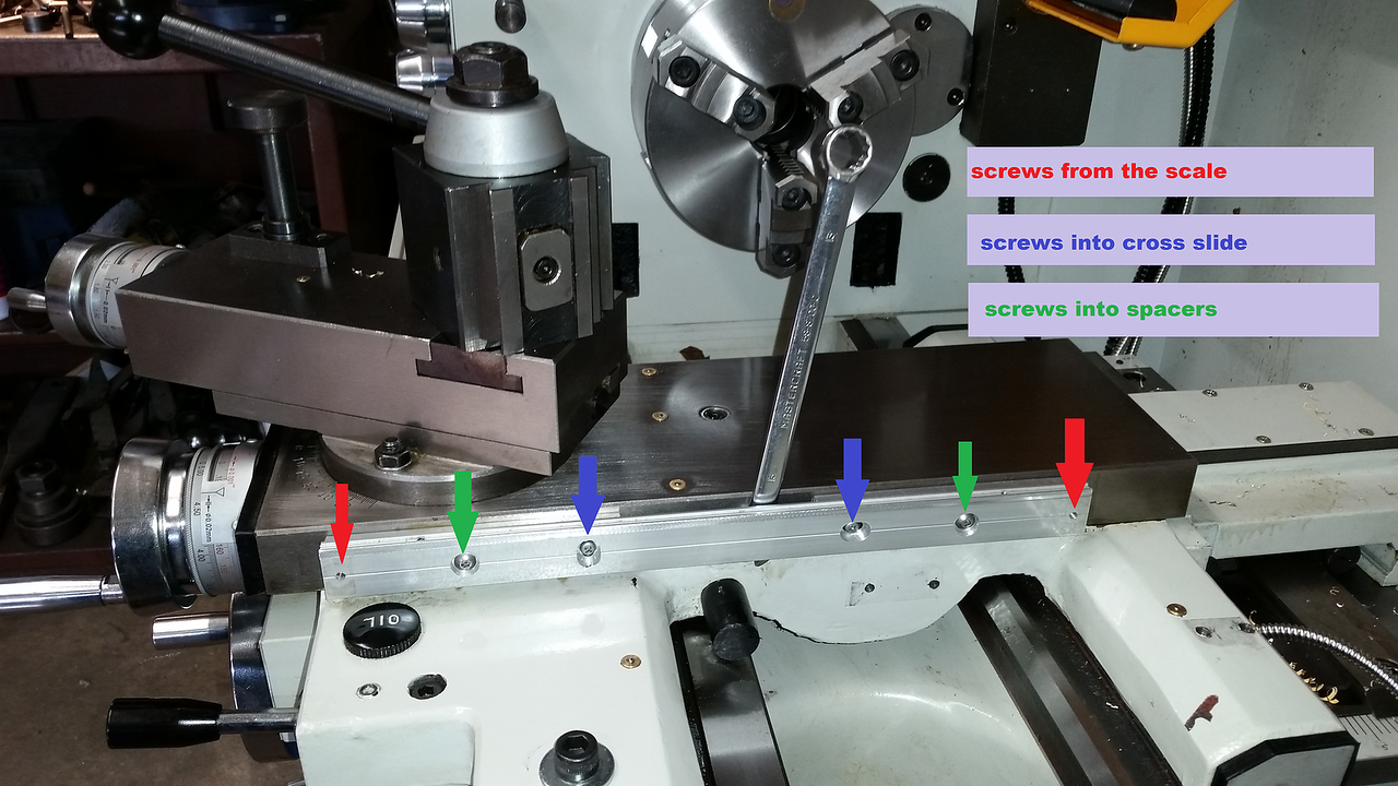
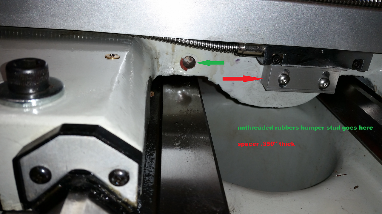
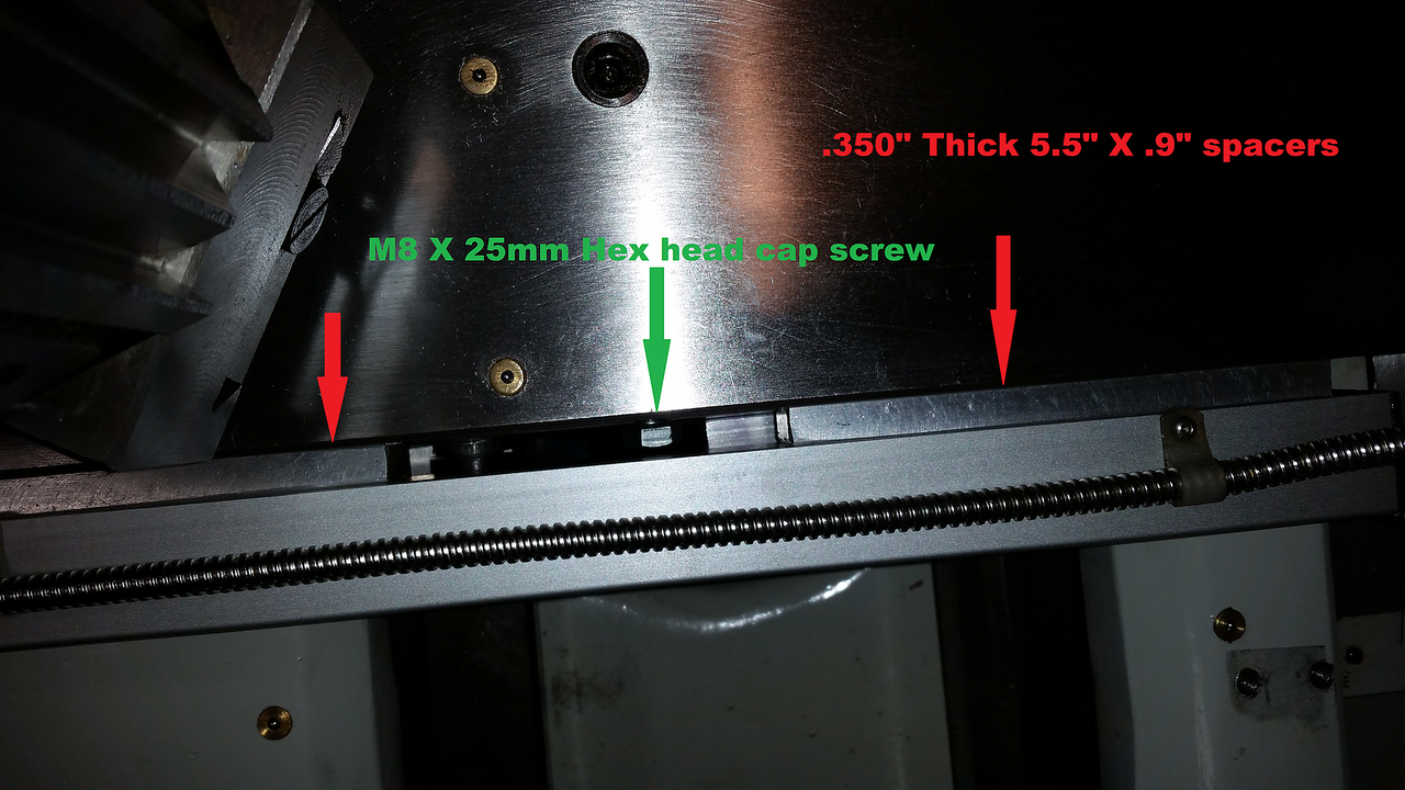
When the DRO was installed the cross slide scale was positioned over top of the locking screw so there was no access to lock the cross slide. That bothered me as I often used that on my old lathe. I removed the scale and machined some spacers to move the scale away from the cross slide .350" and machined an 8mm hex head bolt with a brass tip for the lock. There was just a short socket head set screw in the hole originally. There is also a rubber bumper mounted on a stud and fitted into a hole drilled in the cross slide that is meant to prevent the tailstock from hitting the DRO scale. I hade to shim the bumper out 2mm to make it functional.


They had the DRO leads installed by an expert in knot tying so I untangled that mess and added some cable guides to prevent the taper attachment from hitting the cables. There is not enough length to reroute the cable for the chuck shield switch so I will probably rework that later.

It may seem like I'm doing a lot of complaining but I'm really just making fun and having fun improving the new lathe.
Somehow that last pic got out of order but it shows the spacers for the dro and how I screwed then to the original bracket.
I'm sure the machine factory has an "accessories" department where they add the DRO and quick change tool post etc. after the skilled worker manufacture the base machine. Here they employ relatives of the factory owners who need jobs but have absolutely no hand skills, supervision or common sense. lol.
When the DRO was installed the cross slide scale was positioned over top of the locking screw so there was no access to lock the cross slide. That bothered me as I often used that on my old lathe. I removed the scale and machined some spacers to move the scale away from the cross slide .350" and machined an 8mm hex head bolt with a brass tip for the lock. There was just a short socket head set screw in the hole originally. There is also a rubber bumper mounted on a stud and fitted into a hole drilled in the cross slide that is meant to prevent the tailstock from hitting the DRO scale. I hade to shim the bumper out 2mm to make it functional.
They had the DRO leads installed by an expert in knot tying so I untangled that mess and added some cable guides to prevent the taper attachment from hitting the cables. There is not enough length to reroute the cable for the chuck shield switch so I will probably rework that later.
It may seem like I'm doing a lot of complaining but I'm really just making fun and having fun improving the new lathe.
Somehow that last pic got out of order but it shows the spacers for the dro and how I screwed then to the original bracket.
Last edited:
Did you make the bolt with the brass tip or is that something you bought?
Can you put up a pick showing the reinstalled scale with a wrench showing how you would lock to cross slide?
My modern lathe is afflicted with the same issues btw -- I'll be shoplifting your ideas and quickly ..... thx in advance
Sent from my iPhone using Tapatalk
Can you put up a pick showing the reinstalled scale with a wrench showing how you would lock to cross slide?
My modern lathe is afflicted with the same issues btw -- I'll be shoplifting your ideas and quickly ..... thx in advance
Sent from my iPhone using Tapatalk
Kevin I actually got the idea for the cross slide lock from an owners manual on the Precision Matthews site. They have had complaints and show this work around in the owners manual. I made up the brass tipped screw from a M8 X 25mm stainless hex head cap screw and some 3/16' brass rod. I made the length so only 2 threads are left exposed when the screw is tight so I could keep the spacers as thin as possible, just enough space for a 13 mm wrench. The brass end of the screw butts up against the gib to lock the cross slide.
Last edited:
Perfect. Picture #1 was what I was after, I wanted to see the wrench clearance
Sent from my iPhone using Tapatalk
Sent from my iPhone using Tapatalk
Nice mods work. Good example of why some people have such varying results with offshore tool posts under closer inspection. Mine is older gen (KBC) piston but it holds very well. I was considering a wedge but I'm afraid to 'upgrade' it for that reason. The USA ones are damn spendy & they don't come up used very often.
Sketch shows what was wondering about -if you could make a permanent dangle lever, Maybe there isn't enough room.
One thing I dont get is the DRO cables sliding along the bed, is it a gap or a slit in the backsplash? If so how come swarf doesnt go down the gap? I'm thinking of making a plywood mockup for mine & cant get my head around this issue. Mind you Id like to attach it to the bevel on the bottom tray
Attachments

I use Snagit. I got it on promo back when it was reasonable cost. There are others including freeware & I believe snipping tool inside your OS with less features if you just want the basics. Google 'screen capture' for your OS, but just do some review checking & be aware of some crappy ones. Just because it does a job doesn't mean it also doesn't come with bloatware.
I just use Paint that comes with Windows but I have to do them on my PC. I haven't done it on my tablet. Without a mouse it would be a challenge
Never thought about a dangle lever Peter. I'll have to look at that. Here's some pics of the backsplash. The DRO cables drag on the sheet metal and I have to find some way to protect them but they'll be ok for now.


I played with the taper attachment today. The gibs were adjusted way too tight and it wouldn't slide without binding. I backed off the adjustments and worked it back and forth many times with some oil and got it loosened up so it slides. It still seems kind of stiff but I'm sure it will loosen up. Its hard to see the graduations the the units are inches of taper per foot. I set it at 1 inch and moved the carriage 10 inches and the DRO says .97 inches of cross slide movement so it's pretty close. Using this will take some practice. I need to replace all the fasteners, the originals are soft as cheese.
I played with the taper attachment today. The gibs were adjusted way too tight and it wouldn't slide without binding. I backed off the adjustments and worked it back and forth many times with some oil and got it loosened up so it slides. It still seems kind of stiff but I'm sure it will loosen up. Its hard to see the graduations the the units are inches of taper per foot. I set it at 1 inch and moved the carriage 10 inches and the DRO says .97 inches of cross slide movement so it's pretty close. Using this will take some practice. I need to replace all the fasteners, the originals are soft as cheese.
Last edited:
I've decided I like the shield over the chuck. It keeps the oil in a freshly lubed chuck from spraying all over the place. There's an interlock switch so the machine won't run unless the shield is down. That will take some getting used to.
Nice posts John. On my modern 14x40 the taper adjustment angle screw is also intertwined with the locking mechanism. It's a poor design and prevents you from adjusting the angle to a fine level of precision. That is why I ended up using that plastic dial indicator holder on the compound instead. Is your taper adjustment on the new lathe better?
I bought the wedge style QCTP for my old lathe from Precision Matthews and was really happy with it. I'll check and see what their price is for just the tool post, they only have kits on eBay.
I got a package delivered by UPS from Modern on Friday from the company owner. A set of cutting tools and 4 holders, a very nice touch I think.
I got a package delivered by UPS from Modern on Friday from the company owner. A set of cutting tools and 4 holders, a very nice touch I think.
Last edited:
Nice posts John. On my modern 14x40 the taper adjustment angle screw is also intertwined with the locking mechanism. It's a poor design and prevents you from adjusting the angle to a fine level of precision. That is why I ended up using that plastic dial indicator holder on the compound instead. Is your taper adjustment on the new lathe better?
This is my first experience with a taper attachment. I don't think the setting are too precise but it seems repeatable. I ran it back and forth several timesmand the the same amount of cross slide travel in 10 inches every time. It would take some trial and error to the the setting perfect before aI actually cut anything. I'm anxious to try it though.
I'm not familiar with the style your lathe has, can you elaborate?
There are a few more detail items I feel need to be improved before I consider this lathe ready to go to work. The carriage lock was very sloppy, a 10mm bolt through an almost 11mm hole drilled in the carriage and threaded into an L shaped block that had about .040" clearance to the side of the machine way.


I took a page from PeterT's list of improvements on his lathe for the fix. I used a new 27/64" (.421) to clean up the hole to a consistant diameter for it's entire depth. I machined a stud .421" in diameter to be a sliding fit into the hole and added M10 threads to both ends. Then I flipped over the L shaped block and drilled and tapped it M10 (in the proper location unlike how it was done before) and added a hardened washer and stainless acorn nut to the top for a very snug fitting lock with no slop.
A pretty simple fix but its nice that the carriage doesn't move when the lock is applied anymore.
More to come on the rest of the upgrades later.
Last edited:
DPittman
Ultra Member
Oh that looks good! I will have to study that a bit closer when I have time to see if that can be done to my little lathe which has always had a piss-poor carriage lock. Thanks for sharing your experience.There are a few more detail items I feel need to be improved before I consider this lathe ready to go to work. The carriage lock was very sloppy, a 10mm bolt through an almost 11mm hole drilled in the carriage and threaded into an L shaped block that had about .040" clearance to the side of the machine way. You can see the 10mm socket head bolt at the bottom of this pic.View attachment 4623
I took a page from PeterT's list of improvements on his lathe for the fix. I used a new 27/64" (.421) to clean up the hole to a consistant diameter for it's entire depth. I machined a stud .421" in diameter to be a sliding fit into the hole and added M10 threads to both ends. Then I flipped over the L shaped block and drilled and tapped it M10 (in the proper location unlike how it was done before) and added a hardened washer and stainless acorn nut to the top for a very snug fitting lock with no slop.
View attachment 4624View attachment 4625View attachment 4626View attachment 4627
A pretty simple fix but its nice that the carriage doesn't move when the lock is applied anymore.
More to come on the rest of the upgrades later.