-
Scam Alert. Members are reminded to NOT send money to buy anything. Don't buy things remote and have it shipped - go get it yourself, pay in person, and take your equipment with you. Scammers have burned people on this forum. Urgency, secrecy, excuses, selling for friend, newish members, FUD, are RED FLAGS. A video conference call is not adequate assurance. Face to face interactions are required. Please report suspicions to the forum admins. Stay Safe - anyone can get scammed.
-
Several Regions have held meetups already, but others are being planned or are evaluating the interest. The Calgary Area Meetup is set for Saturday July 12th at 10am. The signup thread is here! Arbutus has also explored interest in a Fraser Valley meetup but it seems members either missed his thread or had other plans. Let him know if you are interested in a meetup later in the year by posting here! Slowpoke is trying to pull together an Ottawa area meetup later this summer. No date has been selected yet, so let him know if you are interested here! We are not aware of any other meetups being planned this year. If you are interested in doing something in your area, let everyone know and make it happen! Meetups are a great way to make new machining friends and get hands on help in your area. Don’t be shy, sign up and come, or plan your own meetup!
You are using an out of date browser. It may not display this or other websites correctly.
You should upgrade or use an alternative browser.
You should upgrade or use an alternative browser.
9" Utilathe Follower Rest
- Thread starter YYCHM
- Start date
Johns picture is better than mine. Anyways if the ring has become distorted by quality issue or installation, or the nut seat has become distorted or fouled, then the collet may not seat properly. If you gronk on a collet in a very localized area like its nose, its also possible to distort it. It may still grip but potentially loose accuracy. ER's are more forgiving than 5C & other more restricted size collets, but anyways those could be some things to look for.
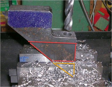
I know this wasn't your question or issue but generally if you ever have the opportunity to clamp things to gain more/maximum contact area, its inevitably better. Less chance of something moving under force, vibration, heat. For example maybe you could shift the part over to the right & deeper in the vise, let the corner hang out the bottom a bit to the side of the vise way. This may not have been possible but you get the idea just eyeballing the potential area difference. This issue is worse yet with unfinished rougher surface vs skim because your nice flat vise jaws see that surface as a bunch of little hill tops, isolated contact points vs the entire projected surface. Anyways, not a critique, just a friendly tip that might extend the life of a tool or part. Sometimes clamping directly across a big (thin wall) hole can create new problems, but thats kind of different again. You have lots of meat in this part.
Attachments
I know this wasn't your question or issue but generally if you ever have the opportunity to clamp things to gain more/maximum contact area, its inevitably better. Less chance of something moving under force, vibration, heat. For example maybe you could shift the part over to the right & deeper in the vise, let the corner hang out the bottom a bit to the side of the vise way. This may not have been possible but you get the idea just eyeballing the potential area difference. This issue is worse yet with unfinished rougher surface vs skim because your nice flat vise jaws see that surface as a bunch of little hill tops, isolated contact points vs the entire projected surface. Anyways, not a critique, just a friendly tip that might extend the life of a tool or part. Sometimes clamping directly across a big (thin wall) hole can create new problems, but thats kind of different again. You have lots of meat in this part.
Ya, a lot of my setups on this one were iffy, it's shape just made it awkward to deal with. Was considering switching to angle plates at one point.
- if you heard the collet go click (installed properly) look to see if the ring is distorted/damaged
I checked my other collets and you're right, they click into place in the nut. All of them, except the 13mm. A closer look revealed that it's badly messed up, inside and out. This will be the second 13mm collet I've replaced?
Last edited:
I checked my other collets and you're right, they click into place in the nut. All of them, except the 13mm. A closer look revealed that it's badly messed up, inside and out. This will be the second 13mm collet I've replaced?
Hey Craig, was wondering why your 13mm collet is messed up where all other appear to work fine and the collet chuck nut seems ok? Sounds strange to me.
Accusize has individual ER style collets see page 31 bottom left of page. Also Page 29 top right for collet chuck nuts. check out their attached catalogue as referenced.
https://accusizetools.com/
Hey Craig, was wondering why your 13mm collet is messed up where all other appear to work fine and the collet chuck nut seems ok? Sounds strange to me.
Probably because I do more 1/2" drilling than anything else. The collets do double duty on both the mill and the lathe and drilling 1/2" and up tends to give me the most grief.
Last edited:
More progress...

Located and drilled and tapped the upright 1/4-20, then assembled for a test fitment. Looks pretty good to me for a mill to the line project. Upright needs to be lowered a smidge.

The easiest thing to setup and do was mill the base legs down a little. Took them down 0.06 in three stages, checking the alignment after each pass.

Looks good to me, I'll think I'll call her done. Support finger locking screws next and maybe counter sink the upright mounting SHCS a bit (that or switch to a flat head screw). I'm also thinking welding the two assemblies together might be a good idea any thoughts?.
Located and drilled and tapped the upright 1/4-20, then assembled for a test fitment. Looks pretty good to me for a mill to the line project. Upright needs to be lowered a smidge.
The easiest thing to setup and do was mill the base legs down a little. Took them down 0.06 in three stages, checking the alignment after each pass.
Looks good to me, I'll think I'll call her done. Support finger locking screws next and maybe counter sink the upright mounting SHCS a bit (that or switch to a flat head screw). I'm also thinking welding the two assemblies together might be a good idea any thoughts?.
Looking good I’d put in a smaller dia 1/4 or 3/8 dia to get a better look at it or if your tool is at centre height use it.
The tool test indicated I was pretty much spot on......
This however indicates I need to come down a bit and right a smidge. Coming down isn't an issue but offsetting right will be.
Worth putzing with?
RobinHood
Ultra Member
Worth putzing with?
Turn your points off center ==> would give you fine tuning adjustability. Then you can leave the frame alone.
Turn your points off center ==> would give you fine tuning adjustability. Then you can leave the frame alone.
That's brilliant..... Have to think on this now. I was planning on cutting a keyway on the support fingers (?don't know if there is a proper name them?) such that locking set screws would enter the keyway rather than mar/damage the finger surface and make future adjustment a challenge. That arrangement would negate the ability to rotate them.
RobinHood
Ultra Member
See about how much off center you need to be. Then either make a small flat (what I would do [& @Tom O is suggesting] and include brass buttons) or turn the point and install. Rotate as required for best alignment. Mark. Mill anti-rotation groove (or a flat as you plan) in the corresponding location. Done.
RobinHood
Ultra Member
If you go for a flat, you can install the fingers and run a part. Put light pressure on the part. Leave it run for a bit without lubrication. the part will leave a nice line where it tangentially contacts your push fingers. The true center of contact is on that line. That will give you a visual indication of how much off of the geometric finger center the contact point is.
See about how much off center you need to be. Then either make a small flat (what I would do [& @Tom O is suggesting] and include brass buttons) or turn the point and install. Rotate as required for best alignment. Mark. Mill anti-rotation groove (or a flat as you plan) in the corresponding location. Done.
Going a step further..... how does one install brass buttons?
RobinHood
Ultra Member
how does one install brass buttons?
Drill a hole in the tip of the fingers. Make an interference fit on the brass pin and press it into the hole. Leave about 1/4” brass sticking out. That would be the simplest way. You could go fancy and machine the brass in the shape of a flat mushroom top: the stem is still an interference fit into the drilled hole. If you miss the fit dimensions, just use red locktite and glue in the tips.
If the tips ever wear out, just cut them off, drill the old brass out of the hole and insert a new brass tip.
How big of a hole for a 1/2" finger?