• Spring 2024 meetup in Calgary - date Saturday, April 20/2024. discussion Please RSVP Here to confirm and get your invitation and the location details. RSVP NOW so organizers can plan to get sufficient food etc. One week to go! More info and agenda
  • We are having email/registration problems again. Diagnosis is underway. New users sorry if you are having trouble getting registered. We are exploring different options to get registered. Contact the forum via another member or on facebook if you're stuck. Update -> we think it is fixed. Let us know if not.
  • Spring meet up in Ontario, April 6/2024. NEW LOCATION See Post #31 Discussion AND THE NEW LOCATION

9" Utilathe Follower Rest

YYCHM

(Craig)
Premium Member
The final thing I'm missing to complete my 9" Utilathe is a Follower Rest. I've been pondering this for months now and spotting a $500US used SM follower on Ebay finally prompted me to make one. @Brent H posted plans for one here 9” and 10” Utilathe Follow Rest Plans | Canadian Hobby Metal Workers & Machinists (Thanks Brent!). Looking at Brent's plans it appears that 1" plate is in order but before chewing my way through this in steel, I decided to mock one up in MDF to check that the dimensions actually work out.

MOD1.JPG

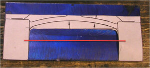
I printed off two views of Brent's plans at 147% scaling.

MOD2.JPG

This gave me a full scale plan of which I could make traceable templates to transfer onto 1" MDF.

MOD3.JPG

MOD4.JPG

This is the mock up. The dimensions on Brent's plan were spot on, and the two part assembly gives some latitude for final adjustment. Since it will be made in 1" thick plate 1/2" fingers seemed appropriate, and those will ultimately be made in 1/2" brass round or steel round with brass tips.

Next step will be to rough out the pieces in steel on the bandsaw.

Craig
 
Last edited:

Johnwa

Ultra Member
For areas that you can’t get to with the bandsaw you can drill a series of closely spaced holes, say 1/4“ holes spaced at 5/16”. They need to be spaced so they are separate holes. Then drill them all out with a 5/16 bit. That should almost separate the pieces. A hacksaw will likely might be required to cut where the holes don’t quite join.
It sounds tedious but it actually goes fairly quickly.
 

YYCHM

(Craig)
Premium Member
For areas that you can’t get to with the bandsaw you can drill a series of closely spaced holes, say 1/4“ holes spaced at 5/16”. They need to be spaced so they are separate holes. Then drill them all out with a 5/16 bit. That should almost separate the pieces. A hacksaw will likely might be required to cut where the holes don’t quite join.
It sounds tedious but it actually goes fairly quickly.

Yup, been there done that before. The U shaped piece of the saddle mount will probably have to be done that way. I'm wondering how well cutting 1" thick plate would go with the bandsaw set in the vertical?
 

YYCHM

(Craig)
Premium Member
Great stuff Craig!!! Glad things worked -
Very hard to design without the actual machine!

Here is a question for you. These plans appear to place the support fingers in direct alignment with the tool post mounting bolt. That pretty much places the tool ahead or behind the support fingers depending upon how you mount the tool. Does that seem right?
 

Brent H

Ultra Member
Yes, you can ride ahead, on or behind depending on application. Ahead for stock removal and on for say threading. Ends of the supports can be altered as well
 

CalgaryPT

Ultra Member
Vendor
Premium Member
Craig — that's the kind of patience and planning that makes for a successful project. Nice work. Can't wait for the finished rest.
 

YYCHM

(Craig)
Premium Member
Let the gnawing begin......

Saddle1.JPG

Squaring up some 1" plate @kevin.decelles gave me (Thanks Kevin!)

Saddle2.JPG

These are my victims…..

Saddle3.JPG

The plan here is to gut the saddle mount with a series of 1/2" holes. Will see how that goes:rolleyes:
 

PeterT

Ultra Member
Premium Member
Maybe its an optical illusion but eyeballing the pic of wood mockup on your lathe, could you reduce the amount of relief & still clear whatever needs to be cleared?
 

Attachments

  • EDT-2021-06-21 000.jpg
    EDT-2021-06-21 000.jpg
    55.4 KB · Views: 5

YYCHM

(Craig)
Premium Member
Maybe its an optical illusion but eyeballing the pic of wood mockup on your lathe, could you reduce the amount of relief & still clear whatever needs to be cleared?

Actually I've increased the distance between the uprights by 1/8" on each side. My cross slide doesn't fit between them using Brent's dimensions. Also, the cross slide gib screws tend to hang up on the right side upright without some extra space.

Edit: Looks like my scaled drawing for the saddle mount wasn't quite scaled properly. @Brent H's dimension of 3.6250" between uprights is very close to being correct. My template ended up being a little on the small side.
 
Last edited:

YYCHM

(Craig)
Premium Member
Progress......

Saddle (1).JPG

The saddle mount gutting process. My 1/2" drill bit packed it in after 4 holes so I had to switch to a 31/64" bit to finish off the hole drilling.

Saddle (2).JPG

A trip to the band saw and we had most of center material removed.

Saddle (3).JPG

Cleaning up the uprights. I actually consider that end mill to be shot but it's good for side milling still.

Saddle (4).JPG

And the bottom face all cleaned up now.

Saddle (5).JPG

Top end detailing and mounting holes drilled.

Saddle (6).JPG

Mounted on the saddle. Everything lines up A-OK. On to the other half of this project.
 

Dusty

(Bill)
Premium Member
Hey Craig well done, remember the kids story about the little train, I think I can, I think I can, pause, I knew I could, I knew I could.
 
Last edited:

YYCHM

(Craig)
Premium Member
Do you think this would work?


BSCut.JPG

Or am I courting disaster here? It's too wide to cut horizontally.
 
Top