-
Scam Alert. Members are reminded to NOT send money to buy anything. Don't buy things remote and have it shipped - go get it yourself, pay in person, and take your equipment with you. Scammers have burned people on this forum. Urgency, secrecy, excuses, selling for friend, newish members, FUD, are RED FLAGS. A video conference call is not adequate assurance. Face to face interactions are required. Please report suspicions to the forum admins. Stay Safe - anyone can get scammed.
-
Several Regions have held meetups already, but others are being planned or are evaluating the interest. The Calgary Area Meetup is set for Saturday July 12th at 10am. The signup thread is here! Arbutus has also explored interest in a Fraser Valley meetup but it seems members either missed his thread or had other plans. Let him know if you are interested in a meetup later in the year by posting here! Slowpoke is trying to pull together an Ottawa area meetup later this summer. No date has been selected yet, so let him know if you are interested here! We are not aware of any other meetups being planned this year. If you are interested in doing something in your area, let everyone know and make it happen! Meetups are a great way to make new machining friends and get hands on help in your area. Don’t be shy, sign up and come, or plan your own meetup!
You are using an out of date browser. It may not display this or other websites correctly.
You should upgrade or use an alternative browser.
You should upgrade or use an alternative browser.
10” Utilathe (Miss Metric) Overhaul Repair
- Thread starter Brent H
- Start date
-
- Tags
- standard modern utilathe
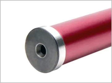
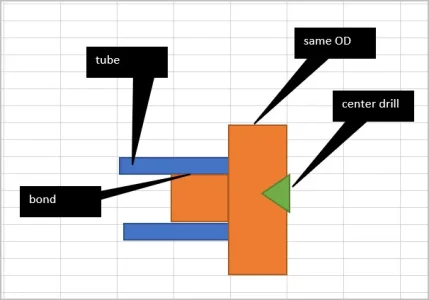
Don't even need solid. The Edge bar is just tubing with ends bonded into ID. All that's important is the collars are turned identically about their center drill, same setting close to the chuck. Make it once & save it as a tool, likely you will use it again in the future.
Attachments
@Susquatch - indeed, using a good Bar for just a simple adjustment is a travesty. Typically they start playing bad music and last call happens just when you are about to get the numbers ….and your “adjustment” needs another Bar …. Just saying - … LOL.
LOL! I know that drill all too well!
OK, I will think something up for this and maybe create a new post if it turns into anything unusual that others might like.
In the meantime it will likely be a cheap piece of black pipe to fit my jaws and two aluminium collars at each end. At the tailstock end I'll add a center to use for setting tapers as well as checking alignment.
Don't even need solid. The Edge bar is just tubing with ends bonded into ID. All that's important is the collars are turned identically about their center drill, same setting close to the chuck. Make it once & save it as a tool, likely you will use it again in the future.
I must be missing something. I don't see how this would work. Don't you have to make a cut at both ends?
I must be missing something. I don't see how this would work. Don't you have to make a cut at both ends?
I haven't figured out how this works either....
It’s basically a dumbbell you just have to make both measurements the same to line up the tailstock.
Ah, I see now. You guys think this is for lining up the tailstock! Not really....
Yes, I'd like to be able to use the same bar to do that too, but that is only a secondary objective. Lining up the tailstock does not require a cut just a measurement across two known identical diameters.
I am after @Brent H 's first task which is to align (or check the alignment of) the spindle with the bed. Unless someone knows something I don't know (which is always highly likely), that requires a cut.
Last edited:
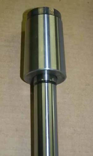
I'm talking about a shop made alignment dumb bell either from solid, or from something like a section of tubing plus separate ends to economize on material. All you need is Loctite to bond the ends. Tubing is actually desirable because it doesn't need to be cut (stress relief) & has plenty of rigidity for this application. Once you have end blanks either center drilled & slightly oversize OD ends, you mount between centers (not a chuck or collet) & take a skim cut over the OD. Preserve that infeed setting exactly, flip the bar & repeat skim cut on other side. They are now centered and parallel. Indicating on the HS side & comparing that to the TS side will indicate in/out & up/down of the TS center. No cutting is ever required beyond making the test bar.
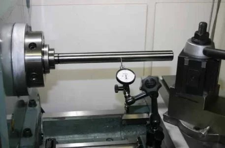
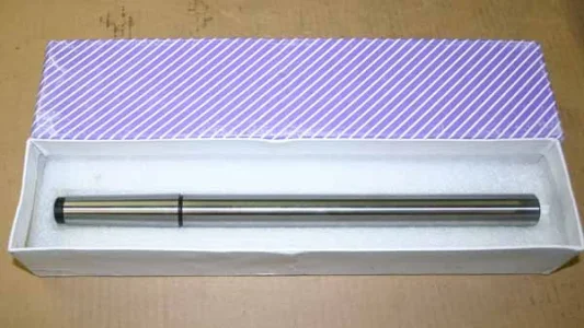
To check spindle alignment relative to bed, the best method I know of is a precision MT taper / parallel bar. The one I bought is MT3 so I use my MT5/MT3 ground adapter that came with the lathe. You can also use this to stick in the tail stock MT socket & do some referencing there independent of the headstock. If you have a completely parallel test bar, it must be gripped by a chuck or something & you introduce potential errors.
To check spindle alignment relative to bed, the best method I know of is a precision MT taper / parallel bar. The one I bought is MT3 so I use my MT5/MT3 ground adapter that came with the lathe. You can also use this to stick in the tail stock MT socket & do some referencing there independent of the headstock. If you have a completely parallel test bar, it must be gripped by a chuck or something & you introduce potential errors.
Attachments
I'm talking about a shop made alignment dumb bell either from solid, or from something like a section of tubing plus separate ends to economize on material. All you need is Loctite to bond the ends. Tubing is actually desirable because it doesn't need to be cut (stress relief) & has plenty of rigidity for this application. Once you have end blanks either center drilled & slightly oversize OD ends, you mount between centers (not a chuck or collet) & take a skim cut over the OD. Preserve that infeed setting exactly, flip the bar & repeat skim cut on other side. They are now centered and parallel. Indicating on the HS side & comparing that to the TS side will indicate in/out & up/down of the TS center. No cutting is ever required beyond making the test bar.
To check spindle alignment relative to bed, the best method I know of is a precision MT taper / parallel bar. The one I bought is MT3 so I use my MT5/MT3 ground adapter that came with the lathe. You can also use this to stick in the tail stock MT socket & do some referencing there independent of the headstock. If you have a completely parallel test bar, it must be gripped by a chuck or something & you introduce potential errors.
What if you just flip the test bar?
Last edited:
Not quite sure what you mean
Why do you need two ends turned to the same OD? Just flip the bar around between the centers?
Ah I see what you mean. Yes if you machined into the bar it would have same OD & serve that alignment purpose. But when you register the DTI ball on the reduced diameter surface A you would also drag it down the length of the larger bar until you get to surface B. The idea is to keep the same indicator position locked, raised (dumb bells) make this easier.
Brent H
Ultra Member
Here are the rough sketches- transferring to AutoCAD and customizing it. I only require the 26 and 30 tooth gears to cover the metric threads the lathe is capable of so I will modify things accordingly. Turns out is is a slick 4.000” from the centre of the gears to the centre of the attachment bolt holes. A nice chunk of 2-1/2” 4140 will make the body.
I keep thinking about buying a cheap 10 TPI lead screw for my Mill Drill and adding new dials. Id do it mostly to improve the selling price, but with proper dials and lead screw, I might even want to keep it......
What is the best way (or at least a good way) to mark the dials for the gradations?
What is the best way (or at least a good way) to mark the dials for the gradations?
RobinHood
Ultra Member
You’ll need a way to index the dial face to the number of graduations. Then you need a way engrave the graduations/numbers.What is the best way (or at least a good way) to mark the dials for the gradations?
If you have a way to index the lathe spindle, you could use it together with an engraving tool held in the tool post. A DH and a milling machine will work. In both cases you’ll have to use number stamps if you want digits on your dial.
A pantograph with a DH, number templates, and an engraving tool would be the old school, preferred method. A CNC mill with a 5th axis would be the modern way.

