• Spring 2024 meetup in Calgary - tentative date Saturday, April 20/2024. Other regions are also discussing meet ups. If you want one in your area get going on organizing it! discussion
  • We are having email/registration problems again. Diagnosis is underway. New users sorry if you are having trouble getting registered. We are exploring different options to get registered. Contact the forum via another member or on facebook if you're stuck. Update -> we think it is fixed. Let us know if not.
  • Spring meet up in Ontario, April 6/2024. NEW LOCATION See Post #31 Discussion NEW LOCATION

10” Utilathe (Miss Metric) Overhaul Repair

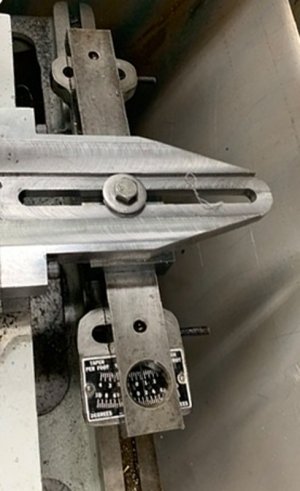
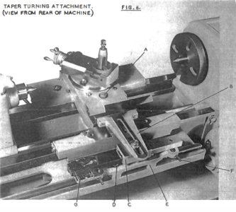
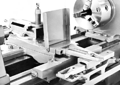
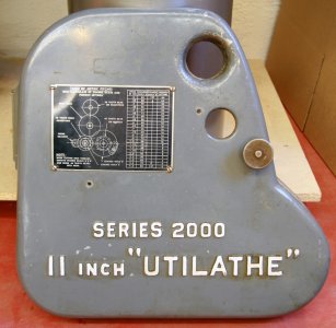
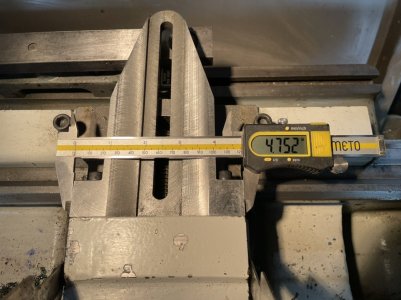
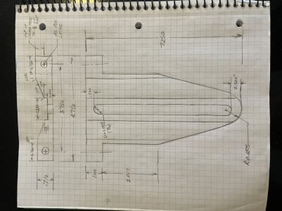
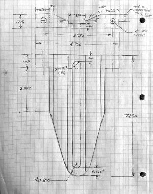
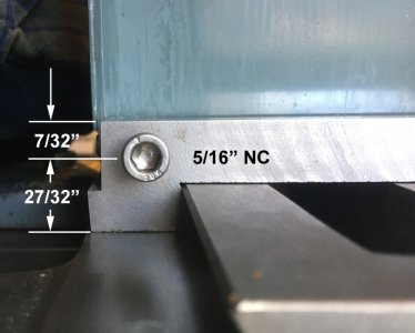
I'm completely off-thread here and wonder if you worked up a drawing for the "cross slide puller" that the taper attachment on a D1-3 11 x 20 Utilathe uses. As seen in the pic, you made the actual part for your 10" machine and I think you mentioned planning to do drawings for the 11" and 12" versions.

I don't know to take a subject off list w/o splashing an e-mail address in front of a billion spammers so if you could contact me I'd appreciate it.

Thx,
Bill @ PEARL, Inc
 

Attachments

  • Cross Slide Puller.jpg
    Cross Slide Puller.jpg
    212.9 KB · Views: 7

Brent H

Ultra Member
Hey @Bill Perkins - I have the drawings for the part in Cad and can scale it for the 1120. All I need is some measurements off your cross slide:

737748CD-1BD4-4568-A472-0CC282B7A624.jpeg
W1= distance between bolt holes
W2 = width of cross slide
T= thickness of the cross slide

Is your 1120 the newer version of the taper attachment or like the one in your picture? If it is the one in your picture it may be that the puller part is the same as the 10/12 one I already made.
 
Mine is exactly like the pix, I can pull dimensions and post this evening. Thx.
 

Attachments

  • SM 1120 Taper Attachment.jpg
    SM 1120 Taper Attachment.jpg
    169.2 KB · Views: 12
  • 11 - Utilathe 2000 Taper.jpg
    11 - Utilathe 2000 Taper.jpg
    184.4 KB · Views: 12
  • Change Gear Cover.JPG
    Change Gear Cover.JPG
    315.2 KB · Views: 10
Last edited:

Brent H

Ultra Member
@Bill Perkins: I think you have an error in the bolt spacing measurement.

Looks like you need the same puller as is fitted to the 10” Utilathe - which makes sense as the 10/12 combination were replaced with the series 2000 11/13 combo and I don’t believe much changed until they changed to the squared off profiles.

Anyway - I am checking my notes for my drawings but here is the rough sketch and some pictures.

You can check here: https://canadianhobbymetalworkers.c...-a-10-ld-utilathe-standard-modern.1475/page-3

When I made the one for my lathe.

D18BDF74-D6F7-4519-8EB5-9B7E739F9A9A.jpeg
EABAE436-CC90-443A-A6E6-50AD0F4631F4.jpeg
46F2A461-CEFD-409F-95BC-229F0E43CD11.jpeg

Let me know if you need more. My CAD program is not opening drawings for some reason. Ugh!
 

Attachments

  • 2F7FC1BC-EE28-4F0A-B72F-31CD9BA1609D.jpeg
    2F7FC1BC-EE28-4F0A-B72F-31CD9BA1609D.jpeg
    234.4 KB · Views: 4
  • D04BEFAB-B4DB-4AC6-A039-3D5E050E2C36.jpeg
    D04BEFAB-B4DB-4AC6-A039-3D5E050E2C36.jpeg
    290.1 KB · Views: 3
  • F7C3F458-2D73-43CC-8376-44282F0A2C65.jpeg
    F7C3F458-2D73-43CC-8376-44282F0A2C65.jpeg
    325.3 KB · Views: 4
  • DEA0ABED-D003-44B3-8AC3-D5F765E8BA14.jpeg
    DEA0ABED-D003-44B3-8AC3-D5F765E8BA14.jpeg
    320.6 KB · Views: 4
Thx for all that, here's your drawing tidied up somewhat. How'd you do the 0.6875" radius at the end, looks to me like a rotary table job?
 

Attachments

  • SM Cross Slide Puller.jpg
    SM Cross Slide Puller.jpg
    568.2 KB · Views: 11

Brent H

Ultra Member
Well, thanks Bill - that is all grinder close to the layout line and file to the line. Setting up the rotary was too much for a small job. I show how I set up the taper cut in the link I stuck in there. I can’t recall if the socket heads are 5/16 or 3/8?
 

Brent H

Ultra Member
Part of the rebuild for a couple Utilathes is to remake the pulley shaft:
897F6B40-633B-42B5-AF91-F9C29DE42145.jpeg

The shaft has an included gear that reduces the spindle RPM to 50 - the slowest speed. The gear is a 17 tooth 16DP 20° PA gear that has a profile shift. This can get confusing and be a pain in the butt to figure out if you only have the one gear. Luckily I have the rest of the lathe.

Essentially, the manufacturer shifts the cutter outward (typically) in order to either accommodate moving the centre line of mating gears or to increase the tooth strength in the gear they are cutting. In this case a typical 17 Tooth 16 DP gear would have an outer diameter of (17+2)/16 = 1.1875”. That would be super except the diameter measure 1.244”. This profile shift allows for the gear to be cut into the shaft and maintain centreline distance to the shaft it runs parallel to as well as increases the base of the tooth profile to maintain strength. As this is the 50 RPM gear it takes a lot of abuse driving the gear train at a reduction from 1725 to 50 RPM.

Material for this shaft/gear will be 4140. Couple high tolerance areas for the bearing and sleeve bushing that also need to be fitted.

The gear cutter for this gear arrived over from England last week and the cutters for the other gears arrived today in the post. Hopefully I will get this all sorted when I get off the ship in a few weeks!
 
I'm playing the lazy card: when you get back is there any chance you could post the CAD drawing of the cross slide puller. I'm vetting a machine shop in China and I'd like to send the guy a real drawing.
Also I found a bearing manufacturer who does ABEC 7 bearings so cheaply I wont' believe it until I see them. But they rep' for Timken, NSK and few other big names so they might be the Real Deal.
The single tapered roller and cone for the headstock spindle for my 11" machine is $US20.00, the rear 6207 2RS is $US2.40 and shipping on those and about 10 others (every bearing in the machine) is $US25.00 with about 14 day delivery. I'll update with details once I have everything in hand.
 

Brent H

Ultra Member
Roger that Bill, let me locate it, verify it and I will send it to you.

If they are cheap - I could use a second one for Miss Metric.

I will correct the cut angle so it looks like the original.
 

Brent H

Ultra Member
Sweet day of making stuff!! I was hoping to show the guys gear making but set up was a bit more lengthy - got some basics discussed but here we go cutting gears. The spec on the shaft is DP 16 PA 20 17 teeth - or Pitch 16, pressure angle 20°, 17 teeth
C292A78D-70AB-42C4-825F-75A2B7A87F31.jpeg
450B5453-B3F6-42ED-952B-012E0AD0E94C.jpeg 870EF8A2-9206-4B34-BAD3-D90AD833187B.jpeg

Next up is the 37 and 26 tooth gear that fits to the shaft (7/8” bore and slides on a 3/16” key)

First shot is cutting in the fap between the gears. Basically part in to the depth - clear it out with a left and right tool.


6CE4C0B8-F64C-4735-8E93-33BE5909535C.jpeg

Ready for teeth:
DB56AF46-18FF-429A-A934-19F1E85D5D08.jpeg
Cutting teeth !!!
14446251-3D15-4491-9E46-FDACE1266F50.jpeg
All going well so far!! Had to stop to cook dinner! (LOL )
 
Looking good man.
I think maybe you forgot about that 3/8" GITS oiler. I did too until the other day and no bigee in any case.
I have just -nuts- quotes back on bearings from China, like an ABEC 7 7304DB - angular contact matched pairs, back-to-back = $US4.00.
I'm like WHAT ! ? 55 year suppliers here in town will want $50.00 and whine about availability and lead times and Covid and what the h*ll am I rebuilding now and God knows what else.
Anyway I'm going buy them and many other sizes at equally impossible prices and advise
 
Top