• Spring 2024 meetup in Calgary - tentative date Saturday, April 20/2024. Other regions are also discussing meet ups. If you want one in your area get going on organizing it! discussion
  • We are having email/registration problems again. Diagnosis is underway. New users sorry if you are having trouble getting registered. We are exploring different options to get registered. Contact the forum via another member or on facebook if you're stuck. Update -> we think it is fixed. Let us know if not.
  • Spring meet up in Ontario, April 6/2024. NEW LOCATION See Post #31 Discussion NEW LOCATION

What's Paul up to?

jcdammeyer

John
Premium Member
Both the original Arduino and the PIC18F series used in my ELS are 8 bit processors. As @PaulL says there are now Arduino compatible processors that are a lot faster using a 32 bit processor and multiple cores. The ESP32 for example has WiFi on one core and you can run your application on the other. I have a box full of different Arduino type modules. Very useful for things like my currently on hold Kiln controller.

The newer Integrated Development Environment (IDE) for the Arduino now offers a little bit of what real IDEs for other embedded systems offer but it's still a toy. At least now you can use break points instead of print statements to debug code. And the library to deal with external devices is frankly amazing.

But, and it's a huge but for embedded systems, not being able to look at the underlying generated assembler is a distinct disadvantage. And those libraries, nice as they are, can leak memory so that 73.6 hours after starting they suddenly reset or freeze. And you have no idea of why or how.

I ported the 8 bit C code into a PIC32 with almost no effort. The interrupt routine that deals with checking ESTOP, runs the on board Micro-Stepping driver, does the trajectory motion changed from taking about 35uS to just over 3uS. A 10x improvement. AdaptorBoard-7.jpg
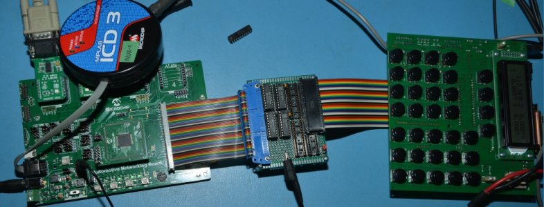
All I needed from the development board was an adapter that translated 3.3V signals to 5V signal levels and moved pins around to match the original 40 pin DIP processor. Ignore U2 and U3 as those are the empty sockets on the board.

For testing the ICD-3 programmer/debugger let me insert break points to stop inside the interrupt routine and even single step the assembler language.

So why the assembler? Each compiler generates and optimizes the code slightly differently. Although Object Oriented Programming (OOP) is very useful at the source code level for programmers to have understandable code, it often creates very slow code. Not a problem with that fast 1000x faster PC. Deciding to make a variable a local, global or object member and looking at how it's used can cut microseconds off your interrupt routine.

So where, although it's rarely mentioned, the Arduino based electronic gearing systems are limited to about 1800 RPM for the spindle because after that the encoder used generates edges too quickly. You can't run it with a 100 line encoder like LinuxCNC and work with 6000 RPM spindles.

The reply from the developers of the Arduino systems are no one uses a spindle above 1800. Lack of I/O is another issue but they seem to like a couple of buttons and a knob for selecting stuff. None of the commerical CNC systems have tiny keypads. Now that there are 32 bit based Arduino modules that may well have changed.

OTOH, there are some pretty nice processors out there like this dual core TI unit. I started porting my ELS to this too just to see how it would work. Still want to try that as it has features the PIC32 doesn't.
Has the hardware encoder modules, CAN bus, etc. and isn't that expensive plus the built in programmer and free IDE.
 

Attachments

  • PIC32_Adaptor.pdf
    40.3 KB · Views: 3

jcdammeyer

John
Premium Member
And for a 32 bit Arduino this is a good start and although it does have CAN bus and multiple PWM for 3 phase motor control I don't see a proper quadrature encoder input module.

Still pretty nice for the money.

edit: I stand corrected. The data sheet for the processor says:
9-channel 32-bit Timer Counter (TC) for capture, compare and PWM mode, Quadrature Decoder Logic and 2-bit
Gray Up/Down Counter for Stepper Motor
 

PaulL

Technologist at Large
Premium Member
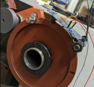
Ok, got a bit more time to poke at my setup, which was reporting slower RPM than the readout on my lathe. So I hacked my way around the physical limitations of my
"count by hand" method. I present you the Kludge-Omatic-RPM counter:
1671587262672.png zer
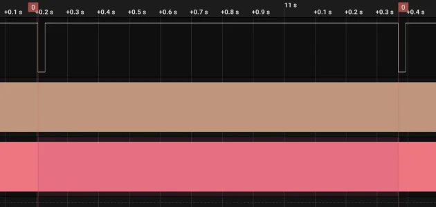
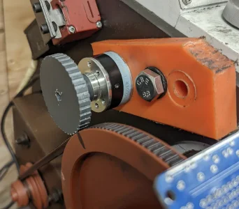
I scabbed a momentary switch onto a PCB I had lying around and zip-tied it to the standoff that holds the cover over change gears, and the lock nuts that space it hold the zip tie well enough to have the little magnetic standoff I put on the spindle pulley very reliably hit the switch. That signal goes to my little Saleae Logic analyzer which is also counting the pulses coming from the encoder hiding behind the gray wheel in the upper left.
1671587176578.png

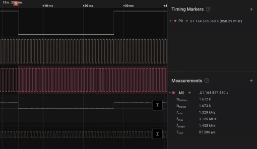
The brown and pink bars are the encoder signals - here's a closeup:
1671587528059.png
The quadrature encoding is clearly visible - the two pulse trains are offset by a half wave. And on the right the nice machine has counted up how many pink edges there are between successive rising edges of Kludge-Omatic input. Checking a few intervals I'm at 1675 +- 3. I'm going with 1675.
 

PaulL

Technologist at Large
Premium Member
And I can see that my little gray wheel is slipping agaist the belt, quite reliably differently at different RPMs. Which isn't surprising - it was a quick cheap hack to get the encoder hooked up. Time to machine a real bracket and pulley. The geometry lets me run it off the drive pulley - I rarely (as in have never) run in the high range, so I don't feel bad committing that belt groove to the task.
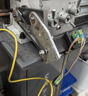
And for good measure, here's a shot of the business end of the rig. The motor will eventually tuck into the back, but it's doing fine hanging off the banjo for now.
1671591222170.png
 

jcdammeyer

John
Premium Member
Ok, got a bit more time to poke at my setup, which was reporting slower RPM than the readout on my lathe. So I hacked my way around the physical limitations of my
"count by hand" method. I present you the Kludge-Omatic-RPM counter:
View attachment 29138zer
I scabbed a momentary switch onto a PCB I had lying around and zip-tied it to the standoff that holds the cover over change gears, and the lock nuts that space it hold the zip tie well enough to have the little magnetic standoff I put on the spindle pulley very reliably hit the switch. That signal goes to my little Saleae Logic analyzer which is also counting the pulses coming from the encoder hiding behind the gray wheel in the upper left.
View attachment 29137

The brown and pink bars are the encoder signals - here's a closeup:
View attachment 29139
The quadrature encoding is clearly visible - the two pulse trains are offset by a half wave. And on the right the nice machine has counted up how many pink edges there are between successive rising edges of Kludge-Omatic input. Checking a few intervals I'm at 1675 +- 3. I'm going with 1675.
Doesn't the encoder also have an index out?
 

PaulL

Technologist at Large
Premium Member
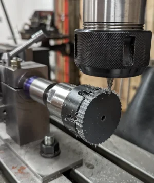
Ok, I got a new encoder gear milled up, and moved it to rest on the spindle drive pulley, both at @jcdammeyer's recommendation:
1671742291436.png
I was able to cut the teeth with a 2mm end mill using my indexing jig and the 40-tooth changegear from my lathe on my indexing jig I made a while back:
1671742378160.png

To date, seems to be less slip, but when I adjust the encoder-to-spindle pulse count to match the lathe's displayed RPM at one speed, I get error at other speeds, indicating a non-linearity somewhere.
The RPM display on the lathe is very laggy - I don't actually trust its output. Next step will be to fit on the opto-coupler that John gave me so I have an index signal, and can use that to get a real RPM count and know I'm measuring the spindle speeds correctly.
And maybe replace that block of orange plastic with some nice aluminium - the plastic deforms more than I like while putting even minor pressure down between the pulleys.
 

jcdammeyer

John
Premium Member
Ok, I got a new encoder gear milled up, and moved it to rest on the spindle drive pulley, both at @jcdammeyer's recommendation:
View attachment 29191
I was able to cut the teeth with a 2mm end mill using my indexing jig and the 40-tooth changegear from my lathe on my indexing jig I made a while back:
View attachment 29192

To date, seems to be less slip, but when I adjust the encoder-to-spindle pulse count to match the lathe's displayed RPM at one speed, I get error at other speeds, indicating a non-linearity somewhere.
The RPM display on the lathe is very laggy - I don't actually trust its output. Next step will be to fit on the opto-coupler that John gave me so I have an index signal, and can use that to get a real RPM count and know I'm measuring the spindle speeds correctly.
And maybe replace that block of orange plastic with some nice aluminium - the plastic deforms more than I like while putting even minor pressure down between the pulleys.
Is it possible that the X:Y multiplication in the pulley sizes is overwhelming the encoder inputs on your RPM measurement? Say the encoder is 800 lines then in quadrature that's 3200 edges per rev. But the encoder is being turned with say an 8" to 2" diameter pulley? (I'm guessing sizes). So that's now 4x the edges per rev.

Unless the v belt is slipping and the teeth in your plastic pulley mesh and there isn't an anomaly in the back side of the belt somewhere then there shouldn't be any slipping. But dropped counts are possible.

When you get the 1 PPR sensor working I can bring over an ELS to read the RPM. And of course your scope can show period.

Edit: Changed seconds to revs. so 12,800 edges per rev with an assumed 1:4 step up ratio. If the spindle is turning 360 RPM then that's 6 revs per second and 76,800 edges per second or about 12uS per edge. That's not a lot of time to count edges although that TI processor you are using could do it in hardware.
 
Last edited:

PaulL

Technologist at Large
Premium Member
Edit: Changed seconds to revs. so 12,800 edges per rev with an assumed 1:4 step up ratio. If the spindle is turning 360 RPM then that's 6 revs per second and 76,800 edges per second or about 12uS per edge. That's not a lot of time to count edges although that TI processor you are using could do it in hardware.
That's the main magic of the TI processor - it does its edge counting in hardware and can report counts since the last time it was polled. So I trust its count.
I actually don't at all trust the RPM meter on my lathe - it takes a very long time - on the order of seconds - to stabilize. Much longer than the acceleration of the spindle.
 

jcdammeyer

John
Premium Member
That's the main magic of the TI processor - it does its edge counting in hardware and can report counts since the last time it was polled. So I trust its count.
I actually don't at all trust the RPM meter on my lathe - it takes a very long time - on the order of seconds - to stabilize. Much longer than the acceleration of the spindle.
I think the scope will be your friend here. The period from the 1 PPR will tell you RPM. The frequency of the encoder output will tell you your ratio and if it's jittering or not.
 

Susquatch

Ultra Member
Administrator
Moderator
Premium Member
To date, seems to be less slip, but when I adjust the encoder-to-spindle pulse count to match the lathe's displayed RPM at one speed, I get error at other speeds, indicating a non-linearity somewhere.

Sounds like lost counts or count/edge deterioration . As others have said, a standalone counter that is polled to get the count is a superior way to do it. Hence my own desire to directly access the Arduino counters and bypass the Arduino interface.

I agree with @jcdammeyer. An oscilloscope is your friend if you have one. If not, use a handheld laser tach and put a full wrap of black tape on the shaft you want to measure as well as a small piece of reflector tape. The black tape will improve signal to noise ratio.
 

jcdammeyer

John
Premium Member
Sounds like lost counts or count/edge deterioration . As others have said, a standalone counter that is polled to get the count is a superior way to do it. Hence my own desire to directly access the Arduino counters and bypass the Arduino interface.

I agree with @jcdammeyer. An oscilloscope is your friend if you have one. If not, use a handheld laser tach and put a full wrap of black tape on the shaft you want to measure as well as a small piece of reflector tape. The black tape will improve signal to noise ratio.
IIRC, the processor board is the TI Launchpad for the F280049C

It has quadrature encoder inputs. So the software has to, on a periodic basis read the counter value.

The key elements then are:
1. The period used to read the counter.
2. The number of periods between counts.
3. The ratio to apply to that counter value to report RPM.

After that it's just math.
 

Susquatch

Ultra Member
Administrator
Moderator
Premium Member

jcdammeyer

John
Premium Member
Oh my! Very sexy development system! Thanks for the link. I've bookmarked it for future reference.

Edit. - I should add that lost counts are not likely with this speedy little system unless the signal quality deteriorates. Ya, a scope will be his friend.
This is the LaunchPad I have:

It has two processor cores along with floating point etc and encoder interface. This was my second choice for updating my own ELS although using the PIC32 would be dramatically cheaper although not as powerful.

I got as far as writing code for communications between the processors but never did get around to connecting an encoder to it. If I ever get the touch pad and probe working together on my milling machine for detecting tool length on the fly I may take this on as a Christmas break project.
 

jcdammeyer

John
Premium Member
According to the Clough42 Electronic Gearing code documentation the RPM is updated 2x per second.
Uint16 Encoder :: getRPM(void) { if(ENCODER_REGS.QFLG.bit.UTO==1) // If unit timeout (one 10Hz period) { Uint32 current = ENCODER_REGS.QPOSLAT; Uint32 count = (current > previous) ? current - previous : previous - current; // deal with over/underflow if( count > _ENCODER_MAX_COUNT/2 ) { count = _ENCODER_MAX_COUNT - count; // just subtract from max value } rpm = count * 60 * RPM_CALC_RATE_HZ / ENCODER_RESOLUTION; previous = current; ENCODER_REGS.QCLR.bit.UTO=1; // Clear interrupt flag } return rpm; }
That parameter RPM_CALC_RATE_HZ is 2 and ENCODER_RESOLUTION is 4096 so
300 RPM would be 10,240 counts in the encoder register every 0.5 seconds. This is 1:1 from spindle to encoder which has 1024 lines for that 4096 edges.

Now if you had an 800 line encoder with 3200 counts per rev with 1:4 ratio to the encoder from the spindle the value for encoder resolution is 12,800 instead of 4096.

Now the code above shows testing for overflow and 32,000/2 is still larger than 12,800 but we haven't actually spun a full scaled encoder rev. Just too fast within the time period I think.

Unless I've screwed up on the math. I suspect the RPM measurements are overflowing.
 
Last edited:

PaulL

Technologist at Large
Premium Member
Yeah,
Oh my! Very sexy development system! Thanks for the link. I've bookmarked it for future reference.

Edit. - I should add that lost counts are not likely with this speedy little system unless the signal quality deteriorates. Ya, a scope will be his friend.
i have my little logic probe living on it now. I think some of the problem is lack of rigidity in the plastic block I have holding the encoder. I'll finish the aluminum replacement this morning and report back.
 

PaulL

Technologist at Large
Premium Member
That parameter RPM_CALC_RATE_HZ is 2 and ENCODER_RESOLUTION is 4096 so
300 RPM would be 10,240 counts in the encoder register every 0.5 seconds. This is 1:1 from spindle to encoder which has 1024 lines for that 4096 edges.
Ok, you've convinced me to check out the overflow handling in detail - yeah, my 600 step (2400 edges ) encoder spinning at ~1700 steps (6800 edges) per rev will overflow a 16 bit counter at as low as 8rpm when sampled every 2 seconds. The symptoms are a off though, as I'm getting within 5% over my whole speed range.
 
Top