Have a look at post #163.
I am sorry to take so long replying to your post. I confess that I have been studying the material you provided in post 163 in my mind all afternoon and all night.
I almost want to keep my mouth shut...... but can't. My own need to understand exceeds the embarrassment of the admission.
I believe the photos and the implications and conclusions Sandvik provides in a few of those photos is wrong......
I know, I know. Who am I to challenge the technical information provided by the likes of Sandvik...... But I've looked at it every which way of Sunday and I keep concluding the same thing.
Perhaps I am missing something. If so, I'd sure like to know what it is.
How can Sandvik be wrong? These characters are insert experts! How can I be right when I am not worthy to walk in their shadow?
Perhaps so, but I know from my own personal experience in the auto industry that the marketing folks often take complicated technical information and turn it into simplified information that is just plain wrong. If I am correct in my assessment of this particular information, then I'd bet that is what has happened at Sandvik too.
Please look at the drawings closely to see if you see what I see. First and foremost, (and what caught my attention in the first place), I see an insert that is cutting air, not metal. There should be metal above the insert that subsequently gets peeled away by the insert. If there is nothing above the insert as shown in their drawings, then there will be no chip. But yet, they show a chip anyway as though it will magically appear out of thin air. In my opinion, the shape and location of the cut section is correct, but only for below the insert. Above it, the shape is also correct but should be shifted to the right by the feed rate. What they show is what it would look like if the feed was disengaged and the lathe left to run for at least one revolution. In this case the cut is already completed, the forces are all gone, and there is no chip.
In my view, the problem that results from this error, is that the resulting forces are shown incorrectly too and so is their derivation and their consequences.
The description completely ignores the downward force on the top of the insert. This force is not minor. In fact, I believe it is the dominant cutting/shearing force by a VERY wide margin. In my mind, it is unreasonable and misleading to ignore this dominant force in any discussion of insert performance and resulting forces. Furthermore, I believe it is the downward cutting force that drives all the issues that we have been discussing here. I'm not saying that the other two forces don't play a role, just that I believe that their role is minor compared to the cutting/shearing force itself. Basically, they guide and direct the cutting force, and I don't think they really do much more than that.
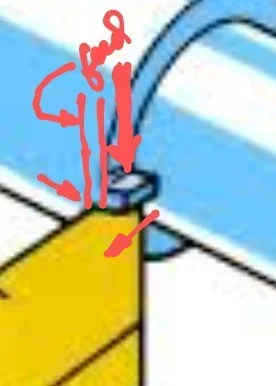
When I think about forces and the structure needed to support those forces, there is no rock of Gibraltar to the right or front of the tool. The vast majority of the support structure is under the tool down through the cross-slide to the bed because that's where the vast majority of the forces are and must be reacted.

