• Scam Alert. Members are reminded to NOT send money to buy anything. Don't buy things remote and have it shipped - go get it yourself, pay in person, and take your equipment with you. Scammers have burned people on this forum. Urgency, secrecy, excuses, selling for friend, newish members, FUD, are RED FLAGS. A video conference call is not adequate assurance. Face to face interactions are required. Please report suspicions to the forum admins. Stay Safe - anyone can get scammed.
  • The 2026 Calgary Area Meetup is set for Saturday May 30th at 10am. The signup thread is here! Robinhood has graciously offered to host the meetup again this year. Please note that you MUST RSVP to the notice linked above if you wish to come.

Tips/Techniques What are you printing today?

Tips/Techniques
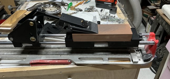
Another use for a ceramic tile cutter.
Making a Canadian copy of a Chinese knife sharpener. Seen on Instagram and thought why not. The clamp pivots to allow the whole blade to be sharpened. Does a fair job with attention to how it works. Just first time a few minutes ago.
Pierre
IMG_1995.jpeg
 
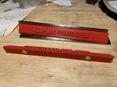
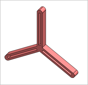
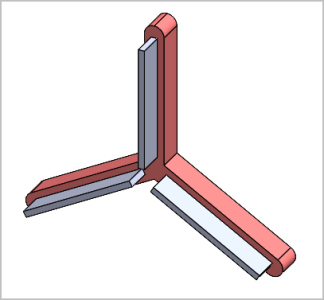
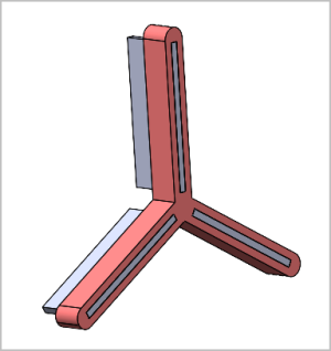
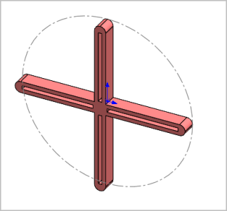
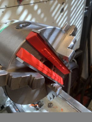
I'm thinking of making a 3DP variant of this. The arms will have close ended slots to receive the parallel bars. Friction fit but semi floating in the slot. Therefore no need for set screws because the part will press the parallels against the chuck face. I cant find (cheap) mini parallel sets in say 3" length & I'd have to buy 2 sets to get 3 of theoretically the same. But actually for what I'm using it for, milling my own parallels would be sufficiently accurate. TBC.

View attachment 85837View attachment 85839

ps - IMHO dont but these, also by Edge. They are not accurate & the magnet installation is poor. And I hate magnets around swarf.
View attachment 85838

Peter I know you don't like magnets - but - this parallel holder lets you use 2 parallels in your lathe so you don't need 3, and it's easy to print. The accuracy comes from your ground parallels not from the printed plastic.
https://canadianhobbymetalworkers.c...allel-holders-15-windsor-on.10273/post-146071

download: https://www.printables.com/model/792597-parallel-holder-for-milling-vise-and-lathe-chucks

IMG_4609.jpeg 1787436704224.png
 
I'm thinking of making a 3DP variant of this

Please do share when done. I prolly couldn't make a decent CAD model so anything you do would be welcome on my printer...

Like you, I think milling is plenty good enough for these parallels. Even though I have a surface grinder, I wouldn't bother using it for this job.
 
this parallel holder lets you use 2 parallels in your lathe so you don't need 3,

2 would be great because we could use existing set of pairs. But dumb question - what stops the holder + steel parallel from sliding out? Its kind of centered so low imbalance, but things happen.

I thought about sacrificing a cheapo 6" set & cutting them in half so you have 3 plus a spare. They are hardened but a disc grinder would get through it. Not sure about heat warpage though.
 
2 would be great because we could use existing set of pairs. But dumb question - what stops the holder + steel parallel from sliding out? Its kind of centered so low imbalance, but things happen.

I thought about sacrificing a cheapo 6" set & cutting them in half so you have 3 plus a spare. They are hardened but a disc grinder would get through it. Not sure about heat warpage though.

Just keep them wet. Or even hold them with a wet rag.

Me? I'd try milling them as a 3pc sandwich from some 1/8 or 3/16 plate.
 
Example 3J & 4J 3DP frame & insert parallel however its achieved. Slots shown are 0.125" wide x 2.5" long x 1" (to be incremented as you prefer).
The arms are completely constrained by the jaws & part if anything decides to go slippy-slidey.


1787441384772.png1787441414888.png1787441826710.png1787441596805.png
 
2 would be great because we could use existing set of pairs. But dumb question - what stops the holder + steel parallel from sliding out? Its kind of centered so low imbalance, but things happen.

I thought about sacrificing a cheapo 6" set & cutting them in half so you have 3 plus a spare. They are hardened but a disc grinder would get through it. Not sure about heat warpage though.
Well, I think that is a concern you're right Peter. I've used them a couple of times and I took the parallels out after I chucked up the stock - they were loose. I'll have to try that again and gently tap the stock in after tightening and see what happens. I added a warning to the printables page - I can't think of a simple solution to keep the parallels captive and the holders captive - so taking them out after tightening the chuck and before you start the lathe seems sensible. Do that folks.
 
I think if I zipped a flycutter accross 3 shop made parallel blanks on the same height setting, they would be within 0.001" if the mill was setup up properly. It doesnt even matter what the height is, its just a matched set of 3 to whatever chuck face offset spacing. They could probably be made of 6061 & work fine, just not as rough & tumble dent resistant.

Another design feature to ponder. If the parallels are closer to center you get more support. Thats fine if you are working on the end of the part. But if its a ring you may prefer over-hole gap like for a boring bar to come through. So maybe the parallel should be shorter than the slot length so you can slide it this way or that. Once its positioned & clamped up it probably wont drift if the slot is relatively snug.

I owe Mr. Edge an apology, mine are some kind of clone, OLM maybe? - not Edge. They differ by 0.002" per leg. The surface is kind of matte pebbly from the annodize coating. The magnets must have been installed with wallpaper paste.
 
But dumb question - what stops the holder + steel parallel from sliding out? Its kind of centered so low imbalance, but things happen.

Could put a tab on the underside that fits into the center hole of the chuck or the slots of the jaws.
Pierre
 
I've used them a couple of times and I took the parallels out after I chucked up the stock - they were loose.

Unless I am missing something they will always be loose. The cantilever design of chuck jaws virtually guarantees it. My practice is to always remove them. In fact, on those few times when I couldn't remove one, I re-did the setup knowing it hadn't released evenly.

Also, I don't think tapping the work with a hammer is as effective as it is on a milling vise. If that level of precision is required, then I use a collet chuck or a dialed in system.

To be honest about it, all we really want here is a better easier faster truer more convenient setup than can be done by eye. In most cases, the OD is still gunna need a skim cut to true it up. If that isn't the case, then the whole concept was prolly overkill. Which is ok I guess as long as we are not fooling ourselves into thinking it's better than that.

Wanting anything more isn't really realistic.

So ya, know that you will need to pull the parallels, pull them, and be happy!
 
Also, I don't think tapping the work with a hammer is as effective as it is on a milling vise. If that level of precision is required, then I use a collet chuck or a dialed in system.
To be honest about it, all we really want here is a better easier faster truer more convenient setup than can be done by eye. In most cases, the OD is still gunna need a skim cut to true it up. If that isn't the case, then the whole concept was prolly overkill. Which is ok I guess as long as we are not fooling ourselves into thinking it's better than that.
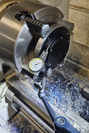
What the stops are intended for, or at least how I use them, is allowing consistent grip of relatively thin parts, especially when thin is combined with larger diameter. Picture a ring 0.2" thick x 1.5" diameter & you have to machine the end. You pick the parallel width that gives you maximum jaw contact but allows just enough stickout to machine the end. So you press the part with machined surface on the parallels while closing the jaws. The part is now perpendicular to spindle axis. Without the stop its very easy to get it cocked a couple thou. The extending surface to be machined is often not suitable or reliable to indicate off which is usually why it needs to be machined in the first place. The stops also make for consistent repeatability if you have multiple parts to make, your DRO measurements are still relevent. It alse acts as a physical constraint to infeed direction turning, very important when the grip contact area is low.

Tapping the part into the parallels in my mind just means super light if you had to overcome say friction fit between parallels & the holder mechanism or you happened to grip the part a thou off one of the parallels, it just seats everything in place. A 5C collet isnt going to grip anything over ~1" dia so very limited range. And 5C actually has just a good chance of grippig something slightly cocked if its thin. You can machine custom holders from emergency chucks or similar, but they are spendy, more suited to smaller diameters & larger production runs.

Chuck body faces are pretty accurate but always measure them to be sure. If the face is tilted for whatever reason, that can only transfer to the parallels. The more likely enemy is swarf or junk between surfaces. Which is why I dislike stops with magnet retention. They attract swarf which is PITA to remove & will easily jack yp the arm rendering in innaccurate. Also watch out for some chucks have grease points or logos or even stickers that extend beyond the chuck face, effectively becomes a shim.
 
What the stops are intended for, or at least how I use them, is allowing consistent grip of relatively thin parts, especially when thin is combined with larger diameter.

Yes, that is what I mostly use the parallels for too.

Yes, a standard collet has a max capacity of an inch or slightly more. But I often make custom collets to do more when needed. They work especially well with the jaws reversed. The jaws hold the collet which holds the work.

You are worried about a thou? I don't think parallels will do that for you when used in a lathe chuck. It's too finicky.
 
You are worried about a thou? I don't think parallels will do that for you when used in a lathe chuck. It's too finicky.

I'm just saying holding a thin part where a small contact area of chuck jaws is providing the grip, is almost guaranteed to not be gripped square to the spindle axis. So if you clamp it cocked its going to get machined cocked. Parallels provide a stable datum to rest the part face on before radial jaw clamping secures it rotationaly. Its no different than holding a thin part in the mill vise unsupported by parallels. You might even set up fine initially, but machining forces have a way of making things move. Down force, stress relief, cutting vibration, temp change, asymetrical cutting operations... Actually a mill vise typically provides much more contact area vs 3 or 4 chuck jaws because stock typically has faces, but I digress

In terms of accuracy, measure it for yourself. Run a DTI accross the face of your chuck body. If it reads 0.0002" and you apply a parallel on top that has a taper runout of 0.0002" you could get a cumulative 0.0004" inclination relative to spindle axis. Thats pretty accurate for a relatively quick setup. I mean if you want more accuracy there are other steps to take of course.

I used the example of facing a large diameter thin ring. Probably a bad example because the ID might be grippable in the jaws if reversed & the jaw steps provide the stop. Again, you can only machine the face if the part width is longer than the step. That could be 10-15mm or more depending on the chuck. If the part is 8mm thick it wont work. But consider a thin + large diameter + solid disc. You have no choice but to grip on OD. Sure, machinable/emergency collets or fixtures have their place. What if the part is 3,4,5" diameter, do you have collets like that?
 
What if the part is 3,4,5" diameter, do you have collets like that?

Relax Peter. We are on the same page. I'm just saying that parallels don't usually get me under a thou.

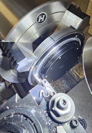
And actually, yes I do have collets for 3,5,6" diameters. I make them. Here is a photo of the last big one I made.


I can also photo the collet itself if you like. I still have it.
 
What if the part is 3,4,5" diameter, do you have collets like that?

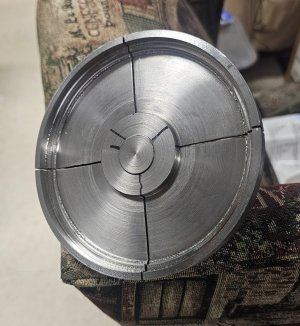
Here is that collet. It is 4-7/8"

20260823_185438.jpg

As you can see, it had a fair of chatter along the clamping diameter. I didn't clean it up because it actually helped hold the part.

The collet was cut on its mounted arbour as a pair so concentricity was excellent.
 
Looks good. Slit collets or pot chucks are also good for holding gears accurately. You cant beat cutting the grip in-situ. I've had to make similar especially if the part has profiles on both sides that require exact concentricity. Or it has to make a detour to the mill, then back to the lathe. I put those in the 'better fixtures' category. More accurate & secure in every respect. Often takes as much effort to make the fixture than the part itself but we do what we have to do. And once you've machined it for a certain diameter or profile, the clamping range is quite limited for future use although they can be repurposed for larger diameters in the future.

The spider/parallel also has its place. Simplicity, rapid setup, accomodates variable diameter & thickness, best for basic facing operations because it will deleiver parallel faces. Most non set-tru chucks don't repeat better than 0.001" TIR so I wouldnt count on a spider setup for that reason alone. Gripping on the end of a jaw is not nearly as secure for anything except light cuts. Sometimes I have to use a 6J for that reason alone. Pros & cons to all methods.
 

Attachments

  • IMG_4029_edited-1.jpg
    IMG_4029_edited-1.jpg
    42.6 KB · Views: 3
  • IMG_4038_edited-1.jpg
    IMG_4038_edited-1.jpg
    46.4 KB · Views: 3
Back
Top