• Scam Alert. Members are reminded to NOT send money to buy anything. Don't buy things remote and have it shipped - go get it yourself, pay in person, and take your equipment with you. Scammers have burned people on this forum. Urgency, secrecy, excuses, selling for friend, newish members, FUD, are RED FLAGS. A video conference call is not adequate assurance. Face to face interactions are required. Please report suspicions to the forum admins. Stay Safe - anyone can get scammed.
  • The 2026 Calgary Area Meetup is set for Saturday May 30th at 10am. The signup thread is here! Robinhood has graciously offered to host the meetup again this year. Please note that you MUST RSVP to the notice linked above if you wish to come.

Tips/Techniques What are you printing today?

Tips/Techniques
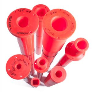
Here is an idea!

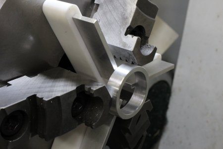
They make these with CNC. It should be, easy peasy to make them on a 3D printer and help tame longer stock on your lathe! Spindle Guides! I e been using rags stuffed in the backside to hold my long stock. These would be waaaay better!

Screenshot_20260824_124951_Chrome.jpg
 
Here is an idea!

They make these with CNC. It should be, easy peasy to make them on a 3D printer and help tame longer stock on your lathe! Spindle Guides! I e been using rags stuffed in the backside to hold my long stock. These would be waaaay better!

View attachment 85946
I found these guys doing just that a couple of years ago

 
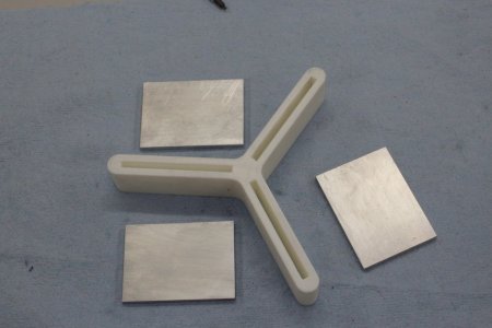
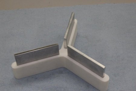
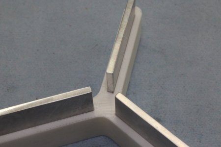
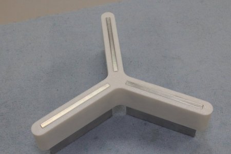
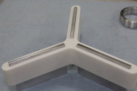
Well the 3DP spider spacer prototype turned out pretty good IMO. One thing I hadnt counted on was the 3DP slot was within a couple thou (amazing actually) but my 2" wide bar of 1/8" aluminum stock for parallel was not very consistent (mostly undersize). So maybe a fancier spider one could use gauge plate (tougher than aluminum) or just mill some thicker stock. Right now it has a firmish sliding fit in the slot. I think this is about right, you want the parallels to be able to move when the part is firmly pressed, bit not loosey-goosey falling out. You can see the 2 back face pictures 1) parallel flush to the 3DP, this was my original thought. But really there is nothing saying the 3DP spider has to be flush. 2) there can be a gap which means less chance for debris to get in there especially embedded on the plastic. The spider is just a carrier to align the parallels. Anyway it performs as expected. No magnets & no set screws. With a standard 3DP I can make a progressive spacer series. I'll run them for a while & see how they perform.
 

Attachments

  • 08-29-2026-001.jpg
    08-29-2026-001.jpg
    88.6 KB · Views: 4
  • 08-29-2026-002.jpg
    08-29-2026-002.jpg
    77.3 KB · Views: 4
  • 08-29-2026-004.jpg
    08-29-2026-004.jpg
    69.4 KB · Views: 4
  • 08-29-2026-005.jpg
    08-29-2026-005.jpg
    76.7 KB · Views: 4
  • 08-29-2026-007.jpg
    08-29-2026-007.jpg
    79.8 KB · Views: 4
  • 08-29-2026-008.jpg
    08-29-2026-008.jpg
    68.2 KB · Views: 4
Well the 3DP spider spacer prototype turned out pretty good IMO.

Beautiful Peter! Cool design. You have to be happy with that!

As I and others mentioned earlier, it would great if you could share the design file and the 3D printer file......

Aluminium is prolly fine. But for myself, I think I would prefer to use steel, stack the three plates together, and run them through my mill and then my surface grinder to get consistent heights.
 
@PeterT how does the holder stay in place while you set the stock into the jaws? I can't tell from the pictures.

With your fingers!

Just put the spider where you want it, place your stock on top, press toward the spindle with your fingers, tighten jaws. Done.

Warning - placing body parts between jaws while tightening may cause loud noises which can be used as an early warning signal to stop tightening.
 
@Susquatch has it right, just press it +/- centered & tighten the jaws. Absolute centering isnt required but helpful if there is mass in the stop. Thats a good thing about 3DP spider. But I found if the part/parallel contact is good the spider stays put. You could give the part a light tap with jaws semi tightened. I thought about a centering boss on the spider to fit my chuck hole, but the jaw blocks can be within the hole depending on the chuck holding diameter, so I just ommitted.
 
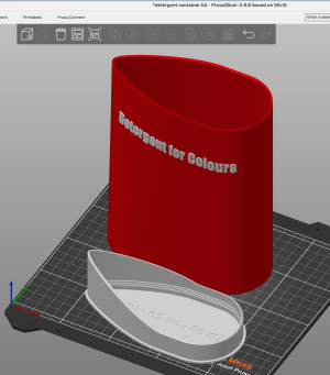
I am printing containers for concentrated laundry detergent. I find a nice model and added a label to it. I finally was persuaded our old washer no longer washed clothes well. So we have a new one, and fancy Deutsch detergent. I have to admit, the new machine does seem to work much better, is quieter, spins faster. We got 16 years or so out of it, along with me repairing a few times. I guess that is pretty good these days.

Screenshot 2026-09-05 at 4.50.37 PM.png
 
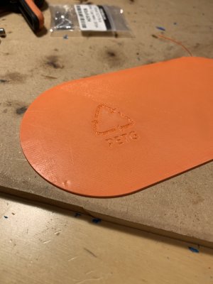
and I posted an improvement request to the Prusa slicer github. Automatic recycling symbol placement. Check it out.. and up vote!


One problem with trying to recycle failed prints is reliably identifying what kind of filament a part is made of. Without a label recyclers frequently are unable to attempt recycling and the print ends up in the landfill. As an enhanced new feature the slicer could automatically, and by default, apply a recycling label to the bottom of the part to be printed using the type of filament assigned to print that part. PLA, PETG, TPU, ASA, etc. Some additional implementation ideas: ....​
​
​
IMG_8892.jpeg​
 
Last edited:
Many years ago I worked in plastic recycling and we would use specific gravity to separate different types of plastics. Like high and low density polyethylene. Some plastics are very close to each other tho and the cost to separate would be very prohibitive. This idea is actually really neat. At one time I was planning on grinding and making my own filament. There was big interest in making filament a couple years ago. Now I try to separate my failed prints. Not to hard as I usually print primarily in petg. I have a tub of failed prints. Maybe one day.
 
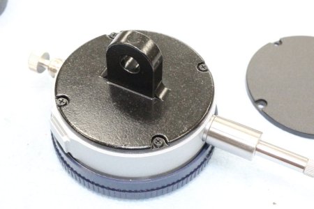
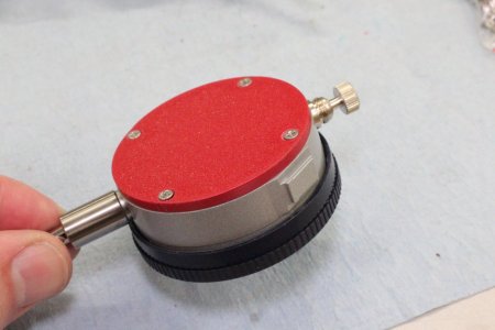
3DP flat coverf for dial indicators. I actually dont use lug backs very much, usually I try to grip the indicator on the stem with appropriate holder. Of course you could keep going with backplate design features like magnet version, maybe dovetail version, or any other kind of benefitial feature for orientating the indicator to work, especially custom situations.

Just a word of caution. If your printer is not dialed in & it doesnt print the screw hole location layout sufficiently accurate, for example an aspect ratio deviation, this can get you into trouble attempting to screw the teeny (typically M2) screws into their holes if they are not lined up perfect &/or proper screw clearance. Dont risk stripping the threaded holes until you are 100% sure they will engage with no cocking or binding. Similarly if your design has lip thickness, be aware of screw length as most of the dials seem to be blind holes 9risk of bottoming out pematurely & stripping threads that way). Some dial bodies have a recess & I think its a good idea to make a matching boss in teh cover plate making it more debris proof. But others, like my Mitutoyo shown, is flat faced.

 

Attachments

  • 09-10-2026-012.jpg
    09-10-2026-012.jpg
    90 KB · Views: 2
  • 09-10-2026-018.jpg
    09-10-2026-018.jpg
    114.1 KB · Views: 2
  • 09-10-2026-023.jpg
    09-10-2026-023.jpg
    78.5 KB · Views: 2
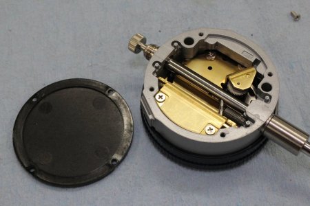
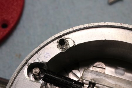
Sidenote. This is the 3rd cover I've made for this POS dial indicator. I thing its an STM or similar bargoon brand. I chocked up my ill fitting machined plates years ago to bad machining on my part. Nope, the 3DP cover is no better. I finally measured accross the screws instead of assuming equal layout. Sure enough this bad boy hole was out by >half a screw width which is why I always only used 3, which is a bit red-necky. Looking inside again, the components & workmanship are Yeesh. My lens keeps popping off & seems to be degrading just sitting in a box. But it was pretty cheap & I think its good to have a kickaboout for a rough duty application. It seems to point at the correct number within its range. If you've ever seen some old Keith Fenner videos where he straightens shafts alternate torch & water hose treatment, sitting in that war zone is a poor dial indicator. Perfect application for cheaper models.

09-10-2026-020.jpg
 
A mag base adapter for the lug or plain back maybe? Something you can put on or take off without tools.

Post step files and I’ll have a go at it.
 
Back
Top