• Scam Alert. Members are reminded to NOT send money to buy anything. Don't buy things remote and have it shipped - go get it yourself, pay in person, and take your equipment with you. Scammers have burned people on this forum. Urgency, secrecy, excuses, selling for friend, newish members, FUD, are RED FLAGS. A video conference call is not adequate assurance. Face to face interactions are required. Please report suspicions to the forum admins. Stay Safe - anyone can get scammed.
  • The 2026 Calgary Area Meetup is set for Saturday May 30th at 10am. The signup thread is here! Robinhood has graciously offered to host the meetup again this year. Please note that you MUST RSVP to the notice linked above if you wish to come.

Tips/Techniques What are you printing today?

Tips/Techniques
Thanks guys,
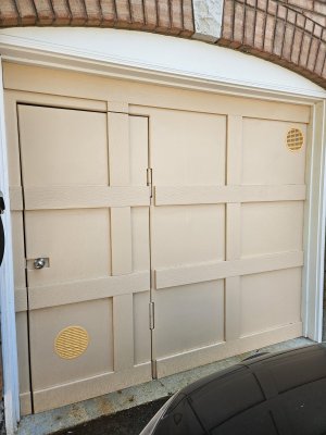
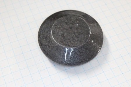
I have these vents I put into my garage door. I printed them out of PLA but the colors don't match. I'll try the primer and latex over it. I don't expect them to last more the a couple of seasons, but I brought them into the world and I cam just make more.
 

Attachments

  • 20260813_120355.jpg
    20260813_120355.jpg
    526.7 KB · Views: 13
Thanks guys,
I have these vents I put into my garage door. I printed them out of PLA but the colors don't match. I'll try the primer and latex over it. I don't expect them to last more the a couple of seasons, but I brought them into the world and I cam just make more.
PLA can last a long time. More if it is sealed and painted. One of my first builds was a pla box that contained a relay, power supply and led. Attached to a float switch to control a sump pump in the corner of our yard to pump out the yard spring and fall. Prior owners of the property destroyed the drainage when the landscaped the yard. The box lasted a long time. It did start to delaminate after a couple years. This was on a post right over the dry well so it was humid as well. as in the elements. I replaced it with a petg one and it last for way more years. I even remade the float in petg and used a magnet and reed switch.
 
Pic? I'd like to see something painted this way.
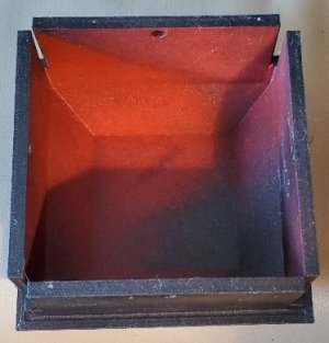
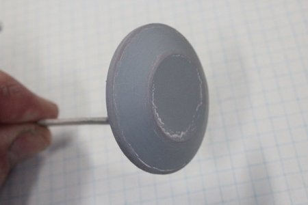
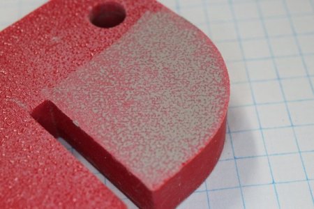
OK. Red PETG. Painted first with primer
20260814_091050.jpg

and then with the Rustomleum.

20260814_092239.jpg

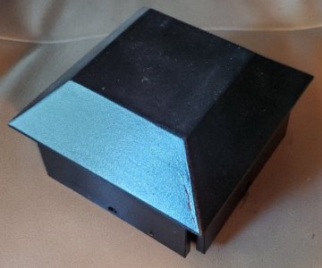
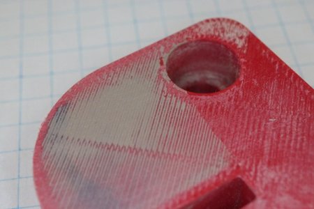
Looked pretty good when I put it on the fence post near the end of May.
20260814_091100.jpg

It sits in direct sunlight where it gets very hot. Notice it's cracked.

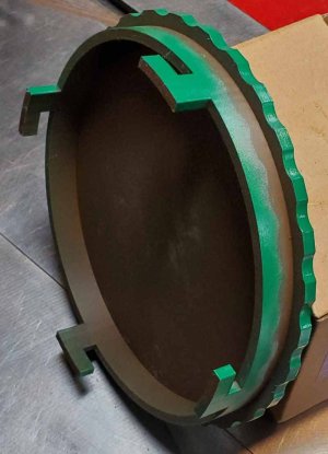
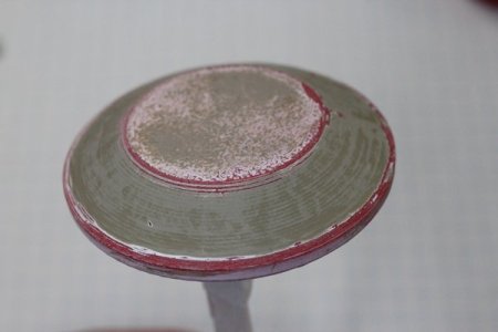
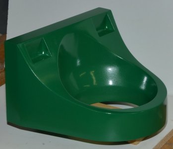
OTOH, This printed in PLA and primer and oil based green paint. Also end of May but a year ago.
SewerCoverBottom.jpg
I've noticed because it's cold underneath due to the hole and sewer cleanout and hot above from the sun that it tends to warp but overall after a year it's still in great shape.
20260814_093136.jpg.

I'd have to print a fence cap out of PLA and use the same primer and paint to see if it would also crack. It sits loosely on the post. As in the post is smaller than the opening.
 
Pic? I'd like to see something painted this way.

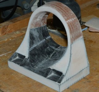
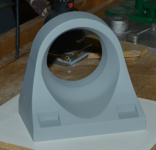
I didnt take many pics of my finishing, I only do it when I have to. But these were in my album showing filler, primer & HammahTime spray bomb on PLA. When I use 3DP to make molds with better finish, its pretty much like this process. Usually when I have excess paint from whatever I'm working on, I'll throw some on scrap 3DP part just for shop R&D. PLA is typical plastic challenges 'sticking' is a relative term. If its not seeing rough duty or wild temperature change, it stays put reasonably well. Hydrocarbon based poducts stick better than water based, at least ones I've tried. I have some Tamiya 'plastic' spray bob stuff I should give that a go one day. There are all kinds of paint products the plastic model crowd uses, moreso water based these days, but of course kind of niche to their application
 

Attachments

  • 30012505.jpg
    30012505.jpg
    32.9 KB · Views: 3
  • 23012502.jpg
    23012502.jpg
    18.4 KB · Views: 4
  • 011908.jpg
    011908.jpg
    25.6 KB · Views: 3
  • 011907.jpg
    011907.jpg
    35.7 KB · Views: 3
  • 011906.jpg
    011906.jpg
    45.1 KB · Views: 3
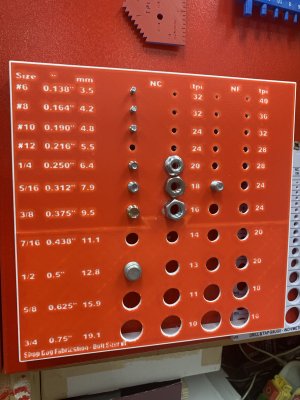
Bolt and nut sizer. This is the fussiest modeling and printing I have done for a while. All the holes are modelled with the right thread, they usually need some tapping as well. In this version I have the entire layer set to white and then the letters are cut into the red. You can print this then with just a filament swap - no need to have a filament changer. This is 0.1mm layer height and the letters are 0.6mm deep. I printed it right side up in 3 pieces. Two parts of the top layer, and the base as another part. Then glue it together. Printing it upside down is simpler but the letters are less clear.

I am testing the letters as different filament. It’s slow and I’m uncertain of the results yet. I’m short a lot of fasteners - especially on the united national fine UNF side. I think a metric one is also called for.
 

Attachments

  • IMG_8800.jpeg
    IMG_8800.jpeg
    1.8 MB · Views: 17
Last edited:
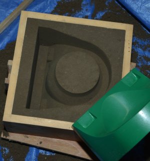
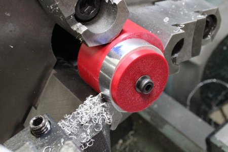
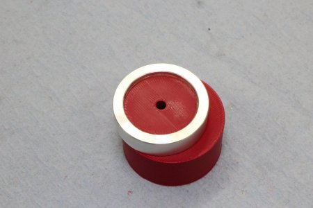
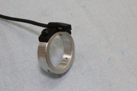
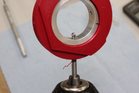
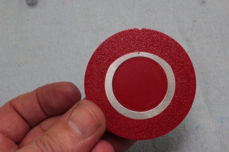
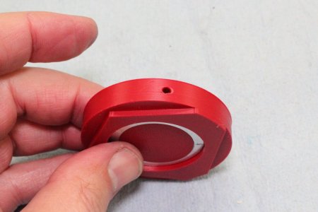
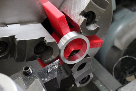
3DP fixtures for a funky shape part. Its basically a ring but has a superimposed wider radius scallop on the top surface. The ID locating boss has the offset cooked in. I printed at 30% infill (PLA) & it held together.
 

Attachments

  • 08-20-2026-030.jpg
    08-20-2026-030.jpg
    119.3 KB · Views: 6
  • 08-20-2026-028.jpg
    08-20-2026-028.jpg
    125.1 KB · Views: 6
  • 08-20-2026-023.jpg
    08-20-2026-023.jpg
    83.4 KB · Views: 6
  • 08-20-2026-018.jpg
    08-20-2026-018.jpg
    90.5 KB · Views: 6
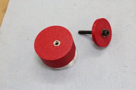
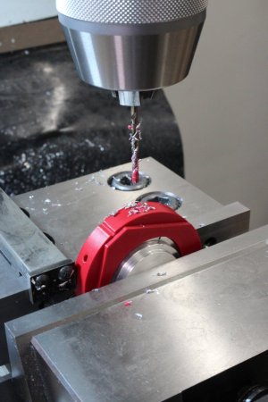
Now the tricky bit. The ring also has 4 radial M3 threaded holes. 2 at 60 deg apart, 2 at 90 deg apart. They need to centered relative to the center axis of the scallop. So I made this fixture which has the matching silouette profile, just push it in, it self aligns. Also has integrated reference datum ledges which sit on a parallel so the hole is always perpendicular. Once I locate one hole, I just rotate the whole fixture, the circle boss is constrained with my vise stop, rinse & repeat. The 3DP center plug is there to give the drill something to break into for a clean exit & also prevent the thin wall ring from distorting under drilling force. Lastly I got brave & just ran the tap in the nice long guide hole with my cordless drill. It tapped just fine which saves yet another setup. Simple looking part but kind of a PITA to make for 1 or 2.

 

Attachments

  • 08-20-2026-038.jpg
    08-20-2026-038.jpg
    83.2 KB · Views: 8
  • 08-20-2026-037.jpg
    08-20-2026-037.jpg
    67.1 KB · Views: 10
  • 08-20-2026-034.jpg
    08-20-2026-034.jpg
    100.8 KB · Views: 8
  • 08-20-2026-033.jpg
    08-20-2026-033.jpg
    107.3 KB · Views: 8
  • 08-20-2026-032.jpg
    08-20-2026-032.jpg
    76.6 KB · Views: 10
Last edited:
Now the tricky bit. The ring also has 4 radial M3 threaded holes. 2 at 60 deg apart, 2 at 90 deg apart. They need to centered relative to the center axis of the scallop. So I made this fixture which has the matching silouette profile, just push it in, it self aligns. Also has integrated reference datum ledges which sit on a parallel so the hole is always perpendicular. Once I locate one hole, I just rotate the whole fixture, the circle boss is constrained with my vise stop, rinse & repeat. The 3DP center plug is there to give the drill something to break into for a clean exit & also prevent the thin wall ring from distorting under drilling force. Lastly I got brave & just ran the tap in the nice long guide hole with my cordless drill. It tapped just fine which saves yet another setup. Simple looking part but kind of a PITA to make for 1 or 2.
What a great print. This is one of the big reasons I love 3d printing. Work holding to drill and tap a couple holes. Before 3d printing you would have had to make a fixture or jig that would take more time to make then the drilling and tapping.
 
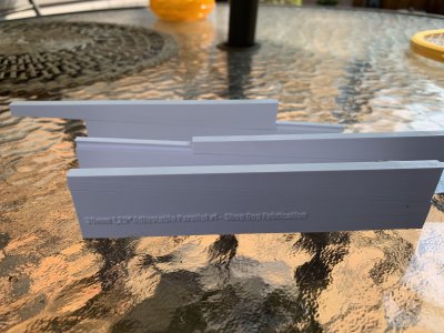
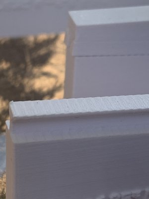
Adjustable parallels? 6mm thick by 30mm tall by 150mm. (~1.25” high) adjustable 4-5 mm. They print better in PLA as the two parts stick or stay in place better than PETG. Look close and you can see the stair steps of the layers on the angles which turns out to be good. The steps give it some resistance to slipping down the ramp. It might need locking screws. The vertical height along the top measures surprisingly consistent.
 

Attachments

  • IMG_8805.jpeg
    IMG_8805.jpeg
    2.7 MB · Views: 8
  • image.jpg
    image.jpg
    867.8 KB · Views: 7
Neat application. Yes you probably want some set screws. They are supposed to be nice & slidey-smooth & then lock on that position. Some people use them in machining setups which is considered bad practice for an 'instrument'. But you now have a disposable instrument so game on LOL.

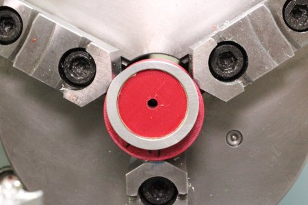
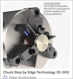
Just be aware of print accuracy limitations. I've mentioned my 3DP chuck spacers before. When my machined part wasnt quite as accurate as I wanted I traced it back to the print, the arms were a bit unequal for whatever reason. Which was actually double-dumb on my part because I was actually expecting that & added extra skin layers so I could chuck it & take a truing pass both sides.
 

Attachments

  • 08-20-2026-016.jpg
    08-20-2026-016.jpg
    115.4 KB · Views: 1
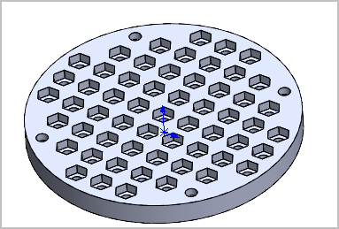
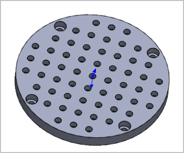
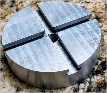
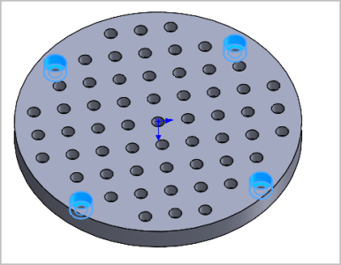
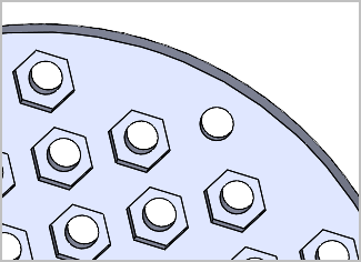
I just sent this STL to a buddy. He has a smallish T-slot chuck for a mini lathe (or rotary table, not quite sure). Might have to tweak some things, but anyway - I made a grid of 10mm spaced holes with M4 nut recesses. Kind of mickey-mouse tooling plate. But actually 3DP fixtures have kind of surprised me as of late & all i've been doing is PLA on medium infill. Its not going to handle interrupted cuts on cast iron, thats for sure, But maybe light duty cutting & for sure indexing on a RT

1787370022517.png1787370046391.png1787370069461.png
 
Last edited:
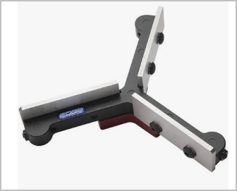
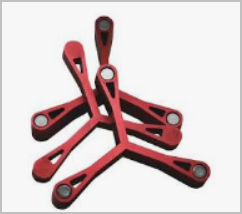
I'm thinking of making a 3DP variant of this. The arms will have close ended slots to receive the parallel bars. Friction fit but semi floating in the slot. Therefore no need for set screws because the part will press the parallels against the chuck face. I cant find (cheap) mini parallel sets in say 3" length & I'd have to buy 2 sets to get 3 of theoretically the same. But actually for what I'm using it for, milling my own parallels would be sufficiently accurate. TBC.

1787370568615.png1787370839657.png

[edit] beware of some of these. My set is not accurate & the magnet installation is poor.
1787454624883.png
 
Last edited:
I just sent this STL to a buddy. He has a smallish T-slot chuck for a mini lathe (or rotary table, not quite sure). Might have to tweak some things, but anyway - I made a grid of 10mm spaced holes with M4 nut recesses. Kind of mickey-mouse tooling plate. But actually 3DP fixtures have kind of surprised me as of late & all i've been doing is PLA on medium infill. Its not going to handle interrupted cuts on cast iron, thats for sure, But maybe light duty cutting & for sure indexing on a RT

View attachment 85834View attachment 85835View attachment 85836
Peter did you want to post your stl or step file. I can see a lot of interest in this one. I know I am.
 
Assume you mean the tooling plate? Here you go. Its a 95mm diameter, which was only because of the smallish T-slot table. If you need a variant just PM me, doesnt take long in CAD. It configurable to different hardware. Like if you have a bag of 6-32 nuts, i would just midify the hex profile or maybe even increase the density. And again - caution. Should be perfectly fine for positioning things on a rotary table. On a lathe, things could go real bad if the material distorts or shears under cutting forces.

Also, the M4 SHCS counterbores (7.5mm dia) were just overlain to 4 outer grid holes so the heads are 1mm below the surface. In retrospect they are maybe a bit close to the edge, again a function of a specific table. They could be relocated to different inner holes.
1787417830569.png1787418588207.png
 

Attachments

Back
Top