• Scam Alert. Members are reminded to NOT send money to buy anything. Don't buy things remote and have it shipped - go get it yourself, pay in person, and take your equipment with you. Scammers have burned people on this forum. Urgency, secrecy, excuses, selling for friend, newish members, FUD, are RED FLAGS. A video conference call is not adequate assurance. Face to face interactions are required. Please report suspicions to the forum admins. Stay Safe - anyone can get scammed.

Welcome to Westwood Metalworks, What is he building in there?

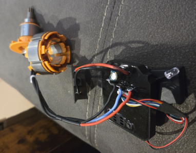
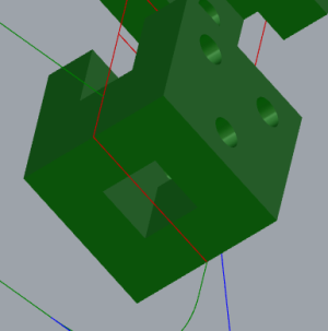
I finished modeling the new brushless motor this morning. Next is to start drawing a housing around it so I can do some test prints to check fitment. I don't really like how the front bearing is tucked inside like it is. That part of the housing will be machined, so it'll be a fun one 😀. Also wondering how the main shaft is assembled because I'd love to press it out, and then press a longer 6mm dowel in there, but I don't want to break it. If the laminations are keyed to the shaft it wont like being pressed. There's no flat running the length, so it might be ok. I might just give it a shot, and if I win I win, if I lose, it's only another $25.....I'm already into this more than buying one from Milwaukee, but then again, they don't make this anyway, so it's all for fun....kinda ( I really want this tool and nobody makes one exactly like it). Yes, I'm purposely being cagey with what it is to save it for a build thread.....😀
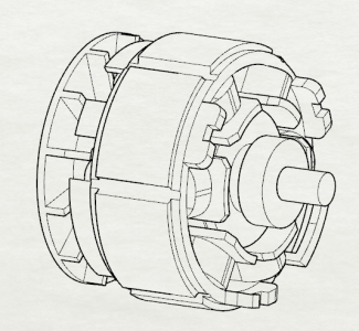
1775135358624.png
1775135463145.png

That'll have to wait as I'm finishing my coffee, then heading outside for some yardwork and to light my big brushpile on fire.
 
Simple 3d printed dimple die to try out the new press. Just some duct metal so nothing to taxing, but worked great.
View attachment 79289
View attachment 79291
View attachment 79292

I only printed the 1/2" pipe die size to try out for now, but designed one for all those knockouts with both a 3/16" radius, and chamfer. I have a few clearance adjustments to make based on the trial, but it worked great. I'm curious to see how they hold up to thicker material and can't wait to test some to failure 😀. Printed with 5 layers top, bottom, and walls, and 30% infill in PETG.
One of the local metal shops here with one of those really long press brakes makes custom dies out of carbon fibre PETG. That way they can form the desired radius on bends without buying or machining expensive steel parts.
 
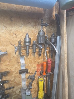
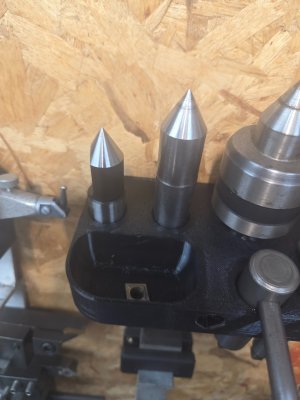
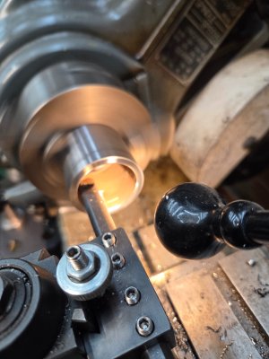
I had to turn a quick fitting for the wife's van windshiedl washer hose yesterday (bulkhead fitting through the hood broke) and got looking at my janky but works lathe tailstock tool storage and thought "I can't do better than that". I mean, it's been working for 10+ years, but I'm on a 3d printing organizational kick right now so......
20260403_082202.jpg

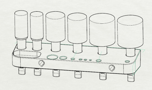
So I spent some time in CAD.
1775221677170.png

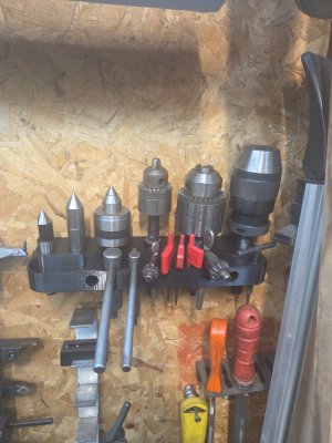
Then hit print. Then woke up to this in the morning. PETG 5 walls and 25% infill. Held on with 2x #8 wood screws. Small tray for when I switch between **gt/**mt insert and need a spot to put them instead of back in the trays.
20260403_082958.jpg
20260403_083000.jpg

File linked below if anybody wants one. Step file too so it's easy to modify to suit your needs better.

I'm going to change the way I do these when it comes to the holes and spots for tooling. I'm going to make the main frame , then for those spots use separate inserts so I can change and modify easier. It's not like I can just drill another hole for something, being that it's not solid. But things change, new tools come and go, so it'll be easier to modify as needed.
 

Attachments

Last edited:
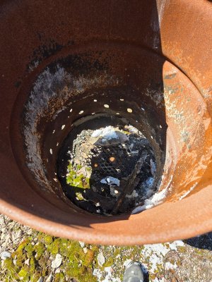
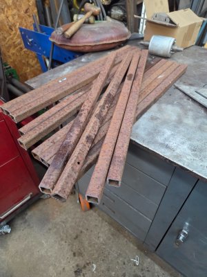
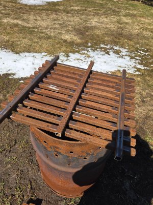
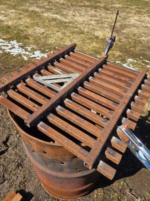
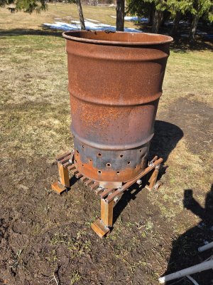
No rocket science here today, just a quick and dirty scrapile build of a "new" burn barrel. The old one served me well for about 12-14 years or so, but the bottom, and subsequent repairs to the bottom have failed me enough times now that it was time to do something better about it.....

20260408_120940.jpg

First quick idea was to weld these 1"sq tubes I salvaged last fall around the bottom rim.

20260408_121637.jpg

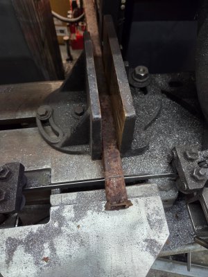
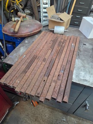
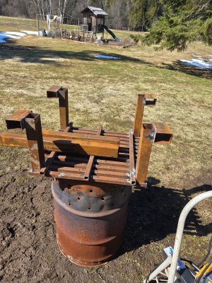
Knowing that's pretty janky and just kicking the can down the road a bit farther I came up with a better idea. Making a completely separate stand, and just have the barrel sit on top. So I started cutting the tubes to a length of 25" (arbitrary # based on the smallest one i could salvage 🙂
20260408_125811.jpg

deburred up the ends and any weld warts from their previous life on the belt grinder.
20260408_130710.jpg
20260408_131046.jpg

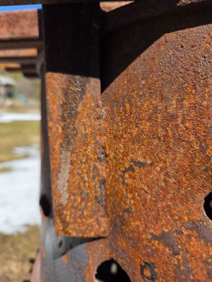
I cut the old bed frame legs off the barrel. This was made back before I even had a sniff of my current shop and welding machines, but the old flux core ugliness still held.....
20260408_121853.jpg

Cleaned "some" rust off of the weld areas and layed them out how I wanted, then started welding. Just one fillet weld down the side. No need to overdo it.

20260408_132200.jpg

20260408_140659.jpg

I used my little Toolium 135 for the entire thing instead of unrolling cables. I wanted to try and use this a bit more and put it through it's paces. Not going to sugar coat it, it really struggled to light up a 3/32 7018 rod on this shitty rusty stuff, but once lit, did a fine job as I expected. I've used a miller suitcase, and a fronius at work quite a few times doing weld repair stuff, on similar rusty junk at cement plants, and the experience is not far off and very similar.......Massive price difference between them all though. For the low price I paid ($90) this thing actually does pretty good. I need to finish making adapter cable to use my good grounds and stinger though. I suspect the experience would be a lot better with both.....

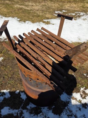
Some more handy scrap produced some legs, and then it was done.
20260408_144942.jpg
20260408_150929.jpg

The barrel is not attached, it's just sitting on the grate, and centered by those welded angles. Hopefully lasts another few years...... I'm still undecided about adding an air tube so I can hook my 18v blower up to it. Just a thought I had while building it...
 
I could have swore I already made up a dinse to lenco connecters to run my regular leads/grounds like the rest of my machines. Like I have the memory formed, and could have swore I posted about it before too. Weird deja vu feeling, but I couldn't find them anywhere. I did find two small dinse connectors, so I just made up a new stinger, and a new ground clamp just for this machine as I had spares anyway. No real change in performance, aside from the fact it's just nicer to use nicer things 😀. Leads are a bit longer, and more flexible too. I did try to run a 1/8" rod with it for the first time. It struggled, but I did light it up, and it did weld ok, but after an inch or so it tripped my garage breaker..... That was another deja vu feeling going back to my old 120v flux core machine days 😀. I could only weld for about 3/4" to 1" before the lights went out.....There's only one 15amp 120v circuit running the entire garage.

Oh well, I didn't buy this to weld big stuff. More on a whim, as I just wanted a nice easy portable machine to run 3/32 with, and it does work well for that. Not as easy starting as I'd like though, but I guess that's a 3/32 on 120v thing? from what I've been reading tonight that seems to be common on 120v machines and echos my experience with the Miller suitcase and Fronius while running on 120v too. I never have a problem with 3/32 on engine drives, 240v, or 600v machines.
 
Last edited:
Rain chased me inside this afternoon, and I felt like starting a "new" project. Not really new, I've had the parts for almost a year, just haven't got to it yet.....


20260410_142159.jpg
20260410_143118.jpg
20260410_143230.jpg
20260410_154510.jpg

20260410_155637.jpg

20260410_155916.jpg

Just scrap offcuts kicking around. All hand shaped on the belt grinder/bandsaw/drillpress and tigged.

I'll do a build thread once I get rolling on it, but in the meantime any guesses?
 
Rain chased me inside this afternoon, and I felt like starting a "new" project. Not really new, I've had the parts for almost a year, just haven't got to it yet.....


View attachment 80873
View attachment 80872
View attachment 80871
View attachment 80875

View attachment 80870

View attachment 80869

Just scrap offcuts kicking around. All hand shaped on the belt grinder/bandsaw/drillpress and tigged.

I'll do a build thread once I get rolling on it, but in the meantime any guesses?
Planishing hammer stand
 
Planishing hammer stand
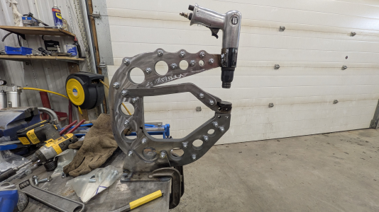
Close. A Japhands Kustoms inspired profiling hammer. Although I'd want it to be able to planish as well.

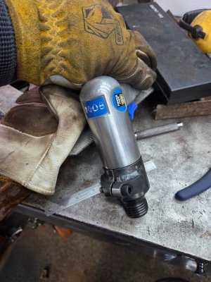
Ever since the first version video came out I've wanted to make one. I bought a long throw air hammer the next time they went on sale, and it's been sitting on my bench for well over a year now. Do I "need" one? No, but I want to make one 😀.

This will be a no CAD build, just figure it out on the bench with whatever material I have. But I have an idea on how I'd like it to look.
 
Close. A Japhands Kustoms inspired profiling hammer. Although I'd want it to be able to planish as well.

Ever since the first version video came out I've wanted to make one. I bought a long throw air hammer the next time they went on sale, and it's been sitting on my bench for well over a year now. Do I "need" one? No, but I want to make one 😀.

This will be a no CAD build, just figure it out on the bench with whatever material I have. But I have an idea on how I'd like it to look.
I'm calling a win on that one. The only difference is the dies you put on it. I ordered the cut files and had it cut by Cutmyparts.ca
Put it together a couple of weeks ago and am just trying to find the time to make some dies for it.
1775870764332.png
 
The dies will be the issue. Having spent the money on the cutting, I'm now too cheap to spend the money on proper dies. The for sale ones are A71 steel but I'm not even sure where to get that, let along being able to cut it to shape. I might try just regular mild steel and try to harden it enough to work. This will not see heavy use in my shop as there are too many squirrels.
 
I was planning on just using regular mild steel for the dies. I can't see it not holding up for the amount I'll be using it. Maybe for some std flange dies I might use some leaf spring, and harden them, but for custom profiles I'm pretty sure mild steel will suffice. I really want to try 3d printed profiles too.

I'm debating on how to make the die holders. Either flat like Karl, or a square shank like pullmax. I might try and accommodate both and give future self options. I really wanted to keep this a simple build, but now I'm thinking about that and want to start modeling something in CAD to figure it out lol.
 
Ughhhh, I can't resist sometimes. I am my own worst enemy at times.

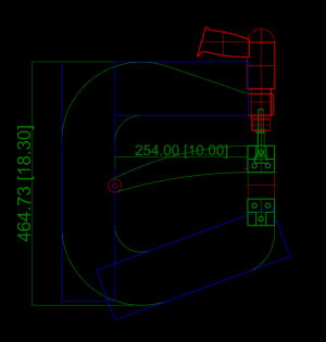
1775913584890.png

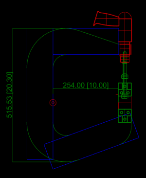
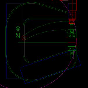
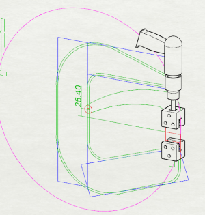
Modeled the air hammer, and collar I made last night, as well as some flat hammers that came with it that I will use to drive the dies, and the longer one as a base for a planishing hammer. Then just started drawing the frame around it using the 10" throat as pretty much my only real constraint. The blue rectangles represent the 3/8" flat stock I have in abundance that I will make the frame from. Still a bit more tweaking and stuff to do, but it's taking shape. I'll be wrapping the inside/outside with 2"x1/4" flatstock to provide torsional rigidity, but mostly to make it look like a cast frame, and to provide some fun for me in building it while providing the look I'm going for.

1775913883666.png1775913908441.png

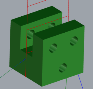
Upper and lower dies will take 3/4" flat stock dies (or thinner if shimmed) plus a 3/4" square shank. Not sure how I'm going to make those yet. Future Dan problem. But the shaper might get the nod there......Or I could file.....Or make it from 2 pieces.....

I'm going to continue on designing this for another hour or so then head out to the shop. Maybe I'll work on this, maybe something else.....squirrelll.......
 
Last edited:
1775914869861.png
I chopped 2" out of it, and I think it looks much better. I'll just machine a custom hammer to strike the dies instead of trying to use the stock short flat face one. Which will no allow my to use the stock short flat one as a plannishing hammer instead of the longer one. Which is probably much better than having all that stickout.....
 
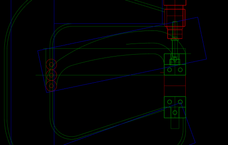
1775916348528.png

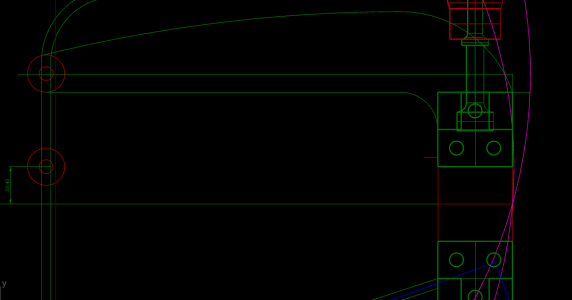
I was trying to keep the pivot point inline with the theoretical split line of the dies, but am thinking about moving it up an inch. I notice on Karls, it's much higher, but closer to center provides the most "inline" action. Struggling to design a tool arm that's aesthetically pleasing and fits the shape lol. Moving the pivot will be for vanity, not for function 😀
 
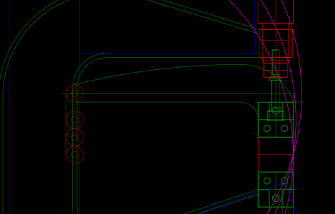
1775917148234.png

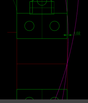
Arm looks much better (in my eyes), but there is a vast difference in the swing profile of the upper die between pivot points as shown by the pink arcs. What to do......

Raising it 1" above the split line gives me I think the best of all compromises, as it allows for the most vertical travel with only 1mm of deflection or in/out swing.

1775917761626.png

1775917791884.png
 
And there we have it.

1775918382972.png
1775918449133.png

All 2d for now except for the parts above. I'd do a quick extrude, then I'm heading outside. Winter was Waaaay too long, and it's waaaaay too nice to be sitting on a couch staring at a screen.
 
Back
Top