• Scam Alert. Members are reminded to NOT send money to buy anything. Don't buy things remote and have it shipped - go get it yourself, pay in person, and take your equipment with you. Scammers have burned people on this forum. Urgency, secrecy, excuses, selling for friend, newish members, FUD, are RED FLAGS. A video conference call is not adequate assurance. Face to face interactions are required. Please report suspicions to the forum admins. Stay Safe - anyone can get scammed.

Machine Vevor MR13A/B Drill Bit Grinder Users

Machine
I have removed that Allen screw holding the grinding disc on, it had no Loctite, just really wrenched on.
I had to use an extension on the end of the Allen key.
 
When I first got mine it had the same issue. IIRC I had to loosen off the motor bolts and slide the unit forward then tighten the bolts back up.
Tried to take the orange cover off. Four screws. Made it loose but wouldn't lift up. Something is in the way. No real motor mount screws on the bottom.
 
Well the latest reply is that their "testing staff" have set up the machine to grind properly and that I just haven't set it up correctly. Here's the message:
Thank you for contacting the VEVOR Support Center.

We greatly appreciate you raising your issue. We value your feedback and hope to help you resolve this problem.
Regarding your feedback, the grinding wheel distance was adjusted by our installation and testing staff based on the actual grinding results, and there shouldn't be a significant difference. Based on the video you provided, we suggest you make a slight adjustment when setting the drill bit; this should resolve the issue.
We sincerely apologize for any inconvenience caused.

Standard stock answer. Now I really do wish I'd ordered from Amazon the way @DavidR8 did. Returns are easy with them.

I've asked to return the unit. I doubt they will do that.

DON'T BUY FROM VEVOR
 
Tried to take the orange cover off. Four screws. Made it loose but wouldn't lift up. Something is in the way. No real motor mount screws on the bottom.

I've had mine all apart. The motor is held to the front plate, not the base.

The cover won't come off if you just remove the front plate. The electrical connection has to come off too. I don't remember exactly how. My memory is good for shit.


Standard stock answer. Now I really do wish I'd ordered from Amazon the way @DavidR8 did. Returns are easy with them.

I have said before that Vevor support sucks. But the product is usually good.

I've asked to return the unit. I doubt they will do that.

I'd ask if it's ok to use some force to remove the wheel. After all, you have to remove the wheel sooner or later. Make it clear that if you damage it in the process, it's still their problem. If they agree, you have that agreement in writing..... you are home free for a replacement.

All that said, the thing really is built like a brick shit house. It can take some abuse.

I have removed that Allen screw holding the grinding disc on, it had no Loctite, just really wrenched on.
I had to use an extension on the end of the Allen key.

I agree that the wheel screw has no loctite. It's the shaft bushing that have loctite.

I used a T-Wrench. Mine came off fairly easily the first time. But I'm a big guy with old man strength. I worry more about breaking things than not being strong enough. Also, the fan is tin foil. I just held the wheel with my left hand and turned out the screw. I've had it off a half dozen times. I still think that a small impact gun on a hex bit is warranted. I would not use an impact driver and hammer.
 
A conflicting thought - If you are getting a good grind on the bit face and the bit cutting edges, that suggests the wheel placement is ok. Otherwise I think there would be a tiny unground centre portion (point) in the middle of the bit. ???

@jcdammeyer - My B doesn't sharpen at the edge. It's close, but not the edge. So I don't think this is an issue. In fact, since the wheel needs to come out which would move the sharpening station further inboard.

i think shimming the split point bracket (or simply adjusting the motor as YotaBota did) would be an interesting and fairly easy project 😎

Messing with these brackets is what @TorontoBuilder was doing. But in this case, the bracket has to move inward. A shim won't do what John needs.

One of the advantages of the B is a moveable collet holder block.
 
I have often purchased from Vevor and had good experiences. I always check what is available from Amazon before buying from Vevor but not necessarily the reverse. I buy from Vevor when the price is much better or the product has features that i can’t find on Amazon. Customer relations at Amazon are a 9+ but below 5 at Vevor. Issue resolution at Amazon are simple but take a lot of effort and can be disappointing at Vevor.
 
I'll go have another look at mine and see how it moved.
You have the VEVOR MR-13A with the orange paint right? So how do you even get at the motor? I took out the 4 screws that hold the centre yellow metal shell but it only lifts up about 1/8".

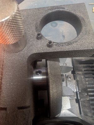
I took my collet holder and a drill bit over to @DavidR8 and we sharpened it on his machine. Without removing the drill bit I brought it home and set it in the relief grinding spot and it doesn't even reach the wheel. Plus the actual split point is to the right of the wheel edge.

20260205_132811.jpg

VEVOR says:
We are deeply sorry for the unsatisfactory service you received. We have forwarded your feedback to our dedicated team and will continue to improve our product.
For the inconvenience this product has caused, would you accept a refund of 100CAD to your original account as compensation?
We look forward to hearing from you.

Before I agree maybe I should take a trip out to Sooke to see what yours does with the same drill bit.
 
Mine arrived today and I got right to work testing it out, went through my drill indexes and sharpened everything that needed attention from 9/16 down to 1/8.

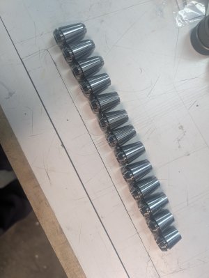
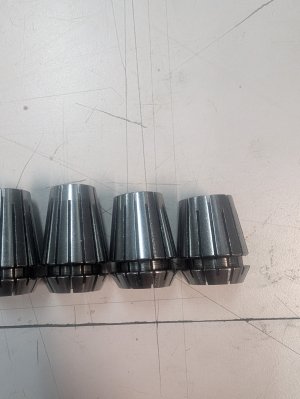
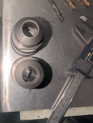
As per requests from Susquatch and CWret, I'm sharing the details of the collets and holders. The collets are all E20 type, at first I saw no difference between the holders but on closer inspection, one has a slightly enlarged bore on the business end - 14.15mm vs 15.2mm. This is obviously to accommodate the largest 14-15mm collet size. I don't know how the larger bore would affect the smaller sizes. The two largest collets are slightly shorter in length due to the enlarged bore. The grinding wheel appears to be the same as in other versions of the 13a, so the only bonus with this two collet set up is the added collets and larger holder.

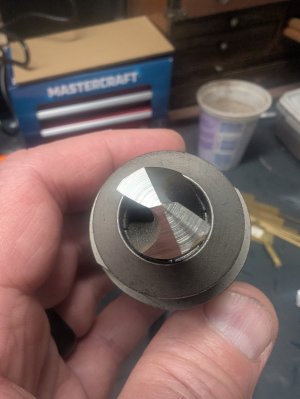
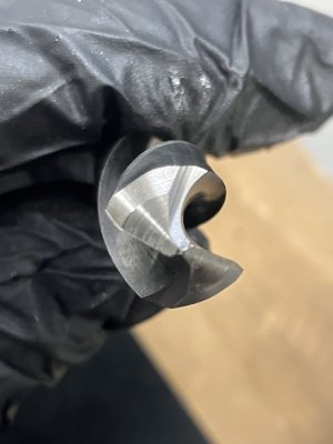
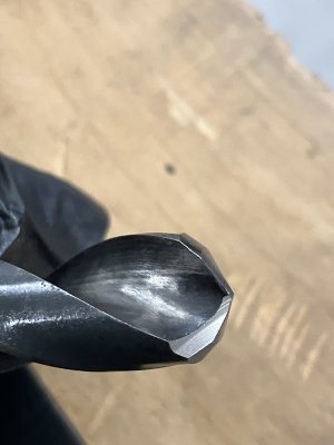
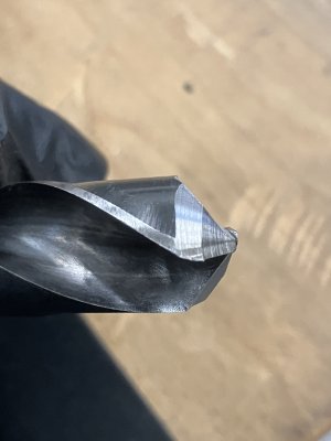
As far as the performance, I'd say it looks pretty decent, the split point appears to be very close to idealPXL_20260205_212258044.jpgPXL_20260205_212631863.jpgPXL_20260205_212640078.jpgPXL_20260205_221606242.jpgPXL_20260205_221623052.jpgPXL_20260205_222027211.jpg
 
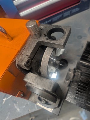
OK. Three years as an OPCE for IBM repairing Selectric Typewriters has paid off. I really didn't want to take this thing apart but after visiting @DavidR8 again and sharpening a bit held in my collet holder on his machine and then checking it on mine showed that ours are not calibrated and assembled exactly the same way.

So time to take it apart.
It's a brushed DC motor with big enough magnets that will grab the screw if you drop on the motor. The centre screw holding the fan and grinding wheel in place needed a 12" flex handle driving the socket screw.

The grinding wheel sits on an aluminum mandrel that is a close sliding fit onto the motor shaft which has only one flat on it. One of the 3 screws clamps onto that. The other two screws 120 degrees apart screw into the shaft, deforming it and making it near impossible to remove the aluminum mandrel

Both the front pivot assembly and the frame holding the motor have to be removed, along with the grinding wheel to get enough torque on the allen wrench to loosen those three screws. They do not appear to be thread locked.

Assembly. Kind of the reverse of disassembly but the wheel will have to come off again in order to screw and torque down the pivot bolt for the front assembly. That's for later.

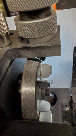
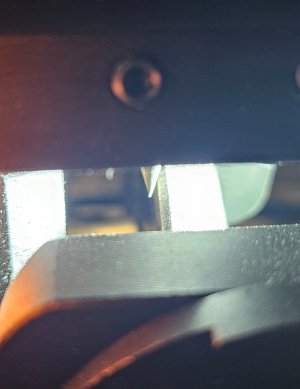
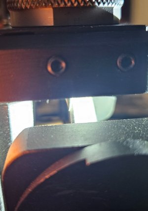
For now only the set screw that goes on the motor shaft flat section is reinstalled. Then the "calibration drill bit" sharpened on David's machine is inserted into the relief grinding hole and the grinding wheel is moved out until there is daylight in the split point gap.

Oh and to do this accurately the height of the drill bit has to be adjusted with the silver knob. Loosed the black setscrew and the pivot screw. Otherwise the spring won't push the assembly upwards. Now it's a process of adjust height and move grinding wheel until the drill bit sits exactly on the stone with no daylight. Tighten the allen set screw to pivot the assembly up against the sliver knob and tighten the clamp screw. Check again the fit of the drill bit against the grinding wheel. Then insert the other two set screws and mark up the shaft some more with them.

Remove the grinding wheel and replace the front pivot assembly. Set it to 118 or 135 degrees matching the calibration drill bit. Move the motor frame in/out until the wheel is just barely scratching the drill bit.
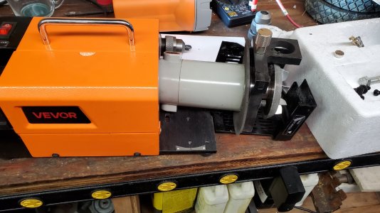
20260205_143623.jpg

Now plug it back in, grab a dull bit and set it into the correct size collet with the cutting edge parallel. First sharpen it. Then do the back relief and split point grinding. If the grinding wheel mandrel is in the correct spot you get this result. Just a tiny overlap creating a small split point.
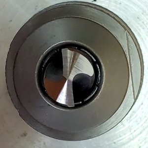
20260205_152701.jpg

Make sure all the screws are tight. Put the guard back on and it's done. Put the collets back into the holders. Best to take them out before you put the machine on its side because otherwise they all fall out. Don't ask me how I know that.

 
Take their $100 and run! Good to hear you're up and running.

I have the 13B. Now that I've had a chance to look at it my problem was with grinding the point, the center of the bit wasn't touching the wheel.
The motor is attached to the split point bracket and the mounting holes for the bracket (on the bottom) were just big enough for me move the bracket and line up the bit with the wheel. This is where I remember the motor moving.
As to removing the SHCS holding the wheel, a quick shot with the 12v Makita hammer drill and off it came.
 
Best to take them out before you put the machine on its side because otherwise they all fall out. Don't ask me how I know that.

I'll never put those collets in those holes in the grinder. I'll make something out of wood to hold them or maybe even wait till the 3D printer arrives. I can't imagine leaving them in the grinder.

Looks to me like you have $100 to put toward something else. The last drill bit you ground looks perfect.

I prolly wouldn't have aligned it up the way you did though. Nobody says your setup fixture is identical to David's. That a bit like setting your tool holder r heights on someone elses lathe. I'd have mounted the drill in my own setting fixture with a 20 or 30 thou feeler gauge like @CWret explained and then set my wheel to that instead of David's setup.

That said, your sharpened drill looks great! Can't argue with the results! Very well done John!
 
I'll never put those collets in those holes in the grinder. I'll make something out of wood to hold them or maybe even wait till the 3D printer arrives. I can't imagine leaving them in the grinder.

Looks to me like you have $100 to put toward something else. The last drill bit you ground looks perfect.

I prolly wouldn't have aligned it up the way you did though. Nobody says your setup fixture is identical to David's. That a bit like setting your tool holder r heights on someone elses lathe. I'd have mounted the drill in my own setting fixture with a 20 or 30 thou feeler gauge like @CWret explained and then set my wheel to that instead of David's setup.

That said, your sharpened drill looks great! Can't argue with the results! Very well done John!
Thanks.
The info at https://canadianhobbymetalworkers.com/threads/how-to-use-vevor-drill-bit-sharpener.18908/
is useful if the grinding wheel is properly placed relative to centerline of the drill bit holder. The feeler gauge for adjusting what will end up being with width of the untouched face is a great idea.

In my case the grinder assembly was incorrect. After I got it going I went back and started adjusting without using the @DavidR8 ground drill bit. What I trial and error headache that was. I finally gave up and went back to using the drill bit.

The problem is with a large drill bit is that a little bit too far doesn't do much harm. But that same setting with a drill bit under 0.25" and suddenly there's way too much of a cut.

Same with the relief grind. The depth needs to be adjusted for smaller or larger drill bits.
 
The one I have is MR-20G. It looks just like the #13, but comes with the second collet chuck and collets to 20mm. It claims “point thinning” instead of point splitting - I believe there is little functional difference between the two (it does mean having to play with the location of the two pins that position the drill for removing the point material (not a big deal).

I like that there I’d a small set screw on the jig to position the bit in the collet - allowing one to set the drill bit out slightly if you want to take more off (the #13 I borrowed for a while didn’t have that feature - easy enough to manage, eye ball out, shim out, drill and tap etc).

Question: has anyone played around with 6 faceting? So three grinds on each face: the main grind, the point splitting and a steep angle at the outer corner. I gave it a go on a 1/2 drill, 135 on the main face, then point splitting, then as pointed as it would go (bit bumps into the collet storage area), around 85ish degrees.

The result was a hole at very close to drill size 0.5005”, and pretty nice surface finish. I believe part of the intent with this approach is that the outer corner is more robust (should last longer?). My interest in trying it is I have a lot of 1/2” holes to drill in the near future (18 holes totalling 30” of material in AR400 plate and 4140 HT, times 50 pieces) - one of my rare revenue jobs.

I’ll certainly call up my main tool supplier and get a couple of their recommended “best” product for the application (when you say that, they can double the price - but if it works great, that’s fine). I thought it would also be a good test for a 6F grind (sort of make me feel like the grinder was worth it if it can make great holes and last a good number of holes).

Comments?
 

Attachments

  • IMG_2441.jpeg
    IMG_2441.jpeg
    1.2 MB · Views: 10
  • IMG_2440.jpeg
    IMG_2440.jpeg
    1.3 MB · Views: 10
  • IMG_2439.jpeg
    IMG_2439.jpeg
    1.2 MB · Views: 11
Comments?

So you got a G! Wow!

That's one of the units I am investigating to add features to the A and B. Prolly going to be bugging you for info, measurements, and photos.

Your web thinning looks just like the web thinning on the B.

I'm afraid I can't really help with whether or not that grind will help you drill that many holes. Quite frankly, my instinct says that it won't because I'd think that it would generate more heat than a standard grind. But perhaps I'm looking at it incorrectly. Maybe that grind requires lower RPM. Lots of things to think about.
 
In my case the grinder assembly was incorrect. After I got it going I went back and started adjusting without using the @DavidR8 ground drill bit. What I trial and error headache that was. I finally gave up and went back to using the drill bit.

This sounds like you still don't have the wheel positioned correctly. Either that or something else is positioned incorrectly.

I mounted a very fine point in the appropriate collet with a slide fit. This allows me to see exactly where the wheel lines up with the various fixtures. In your case with the B model, that pointer should point to the front edge of the wheel from the split point fixture. That pretty much guarantees the correct wheel position. But the collective brain trust will have to confirm that. Particularly @CWret.

In any event, positioning with a drill bit seems like a poor permanent solution. This should be easy, not difficult.

The problem is with a large drill bit is that a little bit too far doesn't do much harm. But that same setting with a drill bit under 0.25" and suddenly there's way too much of a cut.

It isn't clear to me what you mean John.

There is no doubt that you can't setup correctly for a 1/2 inch and expect that to be correct for 1/4. That's the main benefit of using shims - to avoid grind off too much when not needed. That said, it's a lot better to grind off too much than it is to go buy a new drill.... I think that was the manufacturers thinking too.

Same with the relief grind. The depth needs to be adjusted for smaller or larger drill bits.

Ya, same thing. I also found that clocking the bit a quarter skootch more than suggested by the set fixture helped with this too.
 
In my case the grinder assembly was incorrect. After I got it going I went back and started adjusting without using the @DavidR8 ground drill bit.

I mounted a very fine point in the appropriate collet with a slide fit.

Here are some photos.

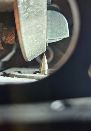
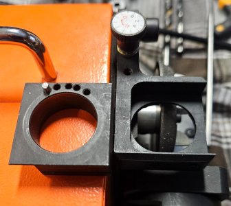
In this pair, I moved the collet holder fixture outward till the point pointed at the wheel edge. The A does not have this adjustment. You have to move the wheel instead. But it should be possible to make something similar that would work on both the A and the B. Having access to a 3D printer would be a huge asset.

This shows my holder too far back.

20260206_153155(1).jpg

This shows the holder moved forward to align the point with the back of the wheel.

20260206_153207.jpg

The pointer is just a piece of Drill rod ground to a point using a rechargeable drill and a bench grinder. Then after grinding to a nice point, I mounted it in one of the grinder collets. The lathe would have been better but I have a job mounted on the lathe right now that I don't want to move.

This photo shows how the point aligns with my stone for general sharpening. Moving the stone rearward a Quarter Skootch would improve drill sharpening.

20260206_151823(1).jpg

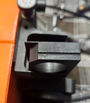
This is the B model Web Thinning indexing block. It can be moved in and out by sliding the block in the fixture. It is held in place with two set screws. It could use a fine adjustment of some kind. It could also use better set screws - these ones are marking up the block.

20260206_160748(1).jpg

20260206_160649(1).jpg

I prefer the no hassle split point capability of the A model, but there are some aspects of the B that could be adapted to the A to improve adjustability and perhaps add web thinning. Conversely, a rear mounted split point system could be added to the B.

These are all things that @TorontoBuilder was investigating until life got in his way. Hopefully his health and personal issues will improve in the near future. My best wishes are with him.

In the meantime, there are lots of things we can do collectively.
 
Back
Top