• Scam Alert. Members are reminded to NOT send money to buy anything. Don't buy things remote and have it shipped - go get it yourself, pay in person, and take your equipment with you. Scammers have burned people on this forum. Urgency, secrecy, excuses, selling for friend, newish members, FUD, are RED FLAGS. A video conference call is not adequate assurance. Face to face interactions are required. Please report suspicions to the forum admins. Stay Safe - anyone can get scammed.

Machine Vevor MR13A/B Drill Bit Grinder Users

Machine
Here are some photos.

In this pair, I moved the collet holder fixture outward till the point pointed at the wheel edge. The A does not have this adjustment. You have to move the wheel instead. But it should be possible to make something similar that would work on both the A and the B. Having access to a 3D printer would be a huge asset.

This shows my holder too far back.

View attachment 77752

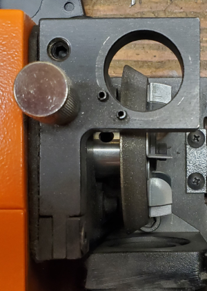
This shows the holder moved forward to align the point with the back of the wheel.

View attachment 77753

The pointer is just a piece of Drill rod ground to a point using a rechargeable drill and a bench grinder. Then after grinding to a nice point, I mounted it in one of the grinder collets. The lathe would have been better but I have a job mounted on the lathe right now that I don't want to move.

This photo shows how the point aligns with my stone for general sharpening. Moving the stone rearward a Quarter Skootch would improve drill sharpening.

View attachment 77755

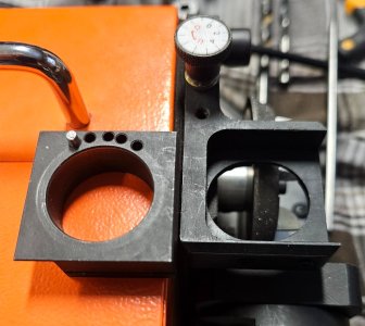
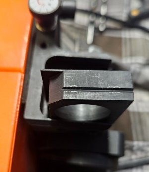
This is the B model Web Thinning indexing block. It can be moved in and out by sliding the block in the fixture. It is held in place with two set screws. It could use a fine adjustment of some kind. It could also use better set screws - these ones are marking up the block.

View attachment 77756

View attachment 77757

I prefer the no hassle split point capability of the A model, but there are some aspects of the B that could be adapted to the A to improve adjustability and perhaps add web thinning. Conversely, a rear mounted split point system could be added to the B.

These are all things that @TorontoBuilder was investigating until life got in his way. Hopefully his health and personal issues will improve in the near future. My best wishes are with him.

In the meantime, there are lots of things we can do collectively.
I totally agree if I understand the photos.

In the MR-13A case the only adjustment for the wheel moves the wheel back and forth. I used feeler gauges to adjust the wheel/motor assembly so that a drill bit set up in the left hand hole where the collet is tightened then when put into the right hand hole touches the wheel and a 0.015" feeler gauge just slips in. So max on each grind is 0.015" off the top of the drill bit.

There is no left/right adjustment unfortunately. Except maybe when the wheel/motor assembly is pressed left or right against the screws that tighten it down. But that's really flaky.

Therefore my only choice was to loosen the wheel mandrel (arbor) from the motor shaft and move it outward about 0.02" or so.

On mine the sliver knob moves the drill bit further away or towards the wheel resulting in less or more relief. Doesn't change where the outboard edge of the wheel sits relative to the collet and drill bit.

It now does a beautiful job of sharpening. My only complaint is I think the quality of the CBN wheel is a little coarse. I see scratches where Davids appear smoother. But if they really do rebate me $100 for all my 'pain' I can buy a new wheel.
 
I’m glad that ( @jcdammeyer ) you are getting a good grind now. That took a lot of effort and we all gained from your experience. Thanks for sharing.
I had a flip-flop through your trouble shooting adventure - first I thought it was the machine calibration - then I guessed it was your bit setup in the holder - then I went back to it’s Vevor’s incorrect machine setup. I’m pleased that Vevor coughed up 100 bucks for your troubles. Plenty (vast majority) of us have been very happy with our grinder right out of the box. Adjusting the motor position to change the grind results was (is) a scary thought- but now, not so much.

I’m in Susq’s camp:
This sounds like you still don't have the wheel positioned correctly. Either that or something else is positioned incorrectly.
but it is hard to argue with good results (a well sharpened bit).

- - - - - -

WOW @Chipper5783 I really like your 6 facing grind idea. My gut feeling is that the complexity of your 6 face grind is not worth the effort and it would not outperform a standard 135 bit, but I commend your creative and novel approach. I recently hand sharpened a 118 degree 1/2” bit to compare it to the same bit that was sharpened using the Vevor. After doing a timed trial (a couple of test holes) I then noticed (measured) the hand sharpen bit and I found that it was not 118 degrees but actually much closer to 90 degrees. My bad! The 90 degree bit drilled a hole ok but it resulted in lots of heat and a poor quality hole (egg shaped). The Vevor sharpened bit was (of course) exactly 118 degrees. (The test holes were in 5/8” mild steel.) I get it that your intent is to have a longer cutting surface at the tip:
the intent with this approach is that the outer corner is more robust (should last longer?).
but from my little experiment with a 90 degree bit - might I suggest that you minimize the portion of the bit face that is 85 or 90 degrees and maximize the portion that is 135 degrees. Knock yourself out with that trial - but I’d be very interested in your results 😎

PS: Further to above - I also compared a 3/4” Vevor sharpened 135 bit to a hand sharpened 135. (As noted elsewhere above - I can now sharpen a 3/4” bit on my 13A thanks to the ER25 special collet holder that Susq sourced). Both holes were good quality and took nearly identical drill times. The hand sharpened bit was very close to the intended 135 angle and it looked very good. The VERY VERY BIG difference is that using the 13A is fast, easy and consistent. Hand sharpening the 3/4” bit took me over 30 minutes and required a steady hand and a good setup on the grinder (+ using CBN wheels). Yes, 30 minutes is a long time, but I was trying to do the best possible hand sharpening for the comparison.
 
I’m glad that ( @jcdammeyer ) you are getting a good grind now. That took a lot of effort and we all gained from your experience. Thanks for sharing.
I had a flip-flop through your trouble shooting adventure - first I thought it was the machine calibration - then I guessed it was your bit setup in the holder - then I went back to it’s Vevor’s incorrect machine setup. I’m pleased that Vevor coughed up 100 bucks for your troubles. Plenty (vast majority) of us have been very happy with our grinder right out of the box. Adjusting the motor position to change the grind results was (is) a scary thought- but now, not so much.

I’m in Susq’s camp:

but it is hard to argue with good results (a well sharpened bit).
It was the wheel position on the motor shaft. Not the motor position. I've asked VEVOR to provide an exploded diagram and parts list.

If I wasn't deep into trying to finish the AR3 Robot arm,, now that I have my drill bits sharpened, I'd pull the think apart and reverse engineer it to create proper drawings. I have in my head what a calibration tool looks like for the grinding wheel and Relief Grinding hole position. Just 1/4" pin with a flat cut on the side inserted into collet. The flat is the distance from the pin centre line for the distance you'd want to the face of the wheel to sit.

But ideally the entire mechanism should be able to be adjusted left/right.
 
I have in my head what a calibration tool looks like for the grinding wheel and Relief Grinding hole position. Just 1/4" pin with a flat cut on the side inserted into collet. The flat is the distance from the pin centre line for the distance you'd want to the face of the wheel to sit.

I like that! A lot! When 5his weather breaks, I'll see if I can make one!

But ideally the entire mechanism should be able to be adjusted left/right.

That is what the B does differently. But I see no reason in the world why that ability couldn't be added to an A with a modified fixture for the collet holder.
 
I like that! A lot! When 5his weather breaks, I'll see if I can make one!


That is what the B does differently. But I see no reason in the world why that ability couldn't be added to an A with a modified fixture for the collet holder.
Haven't looked at that yet. At the moment I'm thinking I'll remake this pattern as a split pattern since the 3 degree taper will still require a 2" long end mill to square off the sides. With a split pattern down the middle I could leave the outside as cast.

But if that's what I do I won't hijack this thread any further. I'll post the results on my projects thread.

1770425107597.png
 
But ideally the entire mechanism should be able to be adjusted left/right.
- yes that would be great. Too bad Vevor didn’t build that into the 13A
But if that's what I do I won't hijack this thread any further
not hijacked IMO - all your discussion has been very relevant and appropriate to this thread
but yes - it would be a good subject for your project thread
 
WOW My gut feeling is that the complexity of your 6 face grind is not worth the effort and it would not outperform a standard 135 bit, but I commend your creative and novel approach. I recently hand sharpened a 118 degree 1/2” bit to compare it to the same bit that was sharpened using the Vevor. After doing a timed trial (a couple of test holes) I then noticed (measured) the hand sharpen bit and I found that it was not 118 degrees but actually much closer to 90 degrees. My bad! The 90 degree bit drilled a hole ok but it resulted in lots of heat and a poor quality hole (egg shaped). The Vevor sharpened bit was (of course) exactly 118 degrees. (The test holes were in 5/8” mild steel.) I get it that your intent is to have a longer cutting surface at the tip:

but from my little experiment with a 90 degree bit - might I suggest that you minimize the portion of the bit face that is 85 or 90 degrees and maximize the portion that is 135 degrees. Knock yourself out with that trial - but I’d be very interested in your results :cool:

[/QUOTE]
I think you are correct about having the 85ish degree portion being quite small, sort of just break the angle (a 0.050” edge). I also agree that the 135 degree bits (with the split point) are great, I converted one of my fractional sets to such an arrangement. The intent being to drill nice holes, not to create artistic drill bits, and the regular 135 grind does make nice holes.

When the drilling project I mentioned earlier comes through and I can get a better idea if it results in a long tool life.

True, it may not be worth the effort, but the effort was small - quicker than the regular grind setup. Practice a few times to figure out a sequence - even the first attempt didn’t take long. Great little grinder.
 
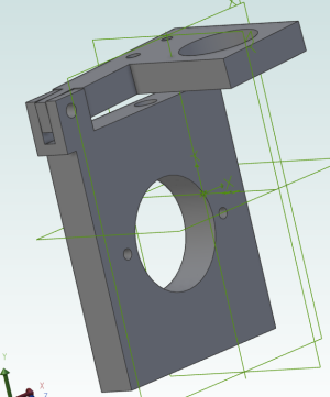
So the dimensions are only approximate in order to present an idea of the model. The motor mount plate has that larger hole for the spring and the chrome adjustment screw. Should be pretty clear that the collet holder fits into the hole with that angle set for the amount of back relief.

The larger hole in the backplate registers the DC motor. Two screws hold the motor in place.

1770455431778.png

Here's the top view. Without taking things apart again I can't quite get the same angle as the drawing.

1770455724383.png

I've included the step file of the assembly. The reason for posting this drawing is to put forward the question that if the motor (and therefore shaft) are fixed relative to the hole for the collet what could be done to change the center line of the collet with respect to the motor shaft end (the arbor for the wheel).

All I see is adjust the wheel on the shaft or add spacers on behind the wheel.
 

Attachments

The reason for posting this drawing is to put forward the question that if the motor (and therefore shaft) are fixed relative to the hole for the collet what could be done to change the center line of the collet with respect to the motor shaft end (the arbor for the wheel).

Exactly! Now the fun begins!

1. If what you want is to adjust the system to work as designed and intended, then moving the wheel to where it should have been in the first place is your only choice.

2. If what you want in an adjustable system, then start with your design and make the collet holder fixture adjustable! Since we know that the B system works, I'd replicate that on the other side. The existing spring and screw will get you up and down, so you need an in and out fixture like the one that comes with the B.

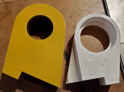
20260206_160748(1).jpg

20260206_160649(1).jpg
 
@jcdammeyer - it should not be too hard to make. A 3D printer should be your friend. The drawing is the hard part I think.
 
I was trying to figure out yesterday, the purpose of the adjusting knob and the hinged spring loaded mechanism on the point splitting function. After loosening the knob I found the pivot to be so tight the plate would not move freely so took it apart and deburred the pivot so that it would move freely when the knob was loosened. Then I experimented with some bits that did not have a split point originally to see what that function did. I found that if i loosened the knob and allowed the plate to rise up, I could insert the holder fully into the plate and then control the depth of the grinding by incrementally tightening it back down until the grind was complete. I figured the purpose of the depth adjustment was maybe just to allow better control of the grinding when doing a split point for the first time on a bit so as to let the holder properly engage in the plate rather than trying to slowly wiggle it down into place.

After thinking on this overnight, I think I came to a realization of how the split point adjustment possibly works. There is the set screw near the knob that determines the maximum depth of the grind, as you increase the depth of the grind due to the angle of the face of the wheel and the position of the bit, it brings the finished facet closer to the mid point of the bit where it should be. Thus, if the split point is off, one simply needs to adjust that set screw to correct the final split point.

I haven't tested this theory yet, but I can verify that the split point did gradually approach the correct position as I incrementally ground the bits until reaching the full depth stop.
 
Ah! So that's how they adjust it. Not a lot of meat on the front side for the set screws. And there's a guide ridge on the inside too?

No, the guide groove doesn't run on a ridge. I think it is intended to engage a pointed or dog point set screw. There is actually plenty enough meat on the front for the set screws.

Personally, I think that aspect could use improvement. For one thing, it needs some kind of fine adjustment.
 
@jcdammeyer - One of the things that needs to be done (and I think that @TorontoBuilder already did it) is to design a B fixture for the A, and an A fixture for the B. It might also be possible to make an A/B fixture. The new A fixture also needs an adjustable block like the B which would have clobbered your issue.

I think we also need to develop a setup alignment procedure for the factory systems and for any modifications we develop.

Notwithstanding your issue, I remain very impressed by these devices. When is the last time you saw a drill bit sharpener with such a thick strong structure? This structure will pay heavy dividends as we start to develop modifications for improvements and new functionality.
 
@jcdammeyer - One of the things that needs to be done (and I think that @TorontoBuilder already did it) is to design a B fixture for the A, and an A fixture for the B. It might also be possible to make an A/B fixture. The new A fixture also needs an adjustable block like the B which would have clobbered your issue.

I think we also need to develop a setup alignment procedure for the factory systems and for any modifications we develop.

Notwithstanding your issue, I remain very impressed by these devices. When is the last time you saw a drill bit sharpener with such a thick strong structure? This structure will pay heavy dividends as we start to develop modifications for improvements and new functionality.
Totally agree. Both @DavidR8 and I have remarked on how heavy and smooth these machines are. It's unfortunate that they torqued the mandrel screws down so hard that they damaged the shaft and now the mandrel won't come off. But the three screws would help if there was a slight wobble in the wheel.

When I have nothing better to do than sit in the evening in front of the TV I may do a more accurate (dimensions) of the bracket system. Include the motor, mandrel and grinding disk in the assembly.

There's not a lot of room back there without modifying the cover to make a larger sliding section. Might be easier to make the pivot at the front different. I find I have to loosen the pivot screw for the back relief depth knob to work. And then remember to tighten it again.
 
It's unfortunate that they torqued the mandrel screws down so hard that they damaged the shaft and now the mandrel won't come off.

Cant you make a small puller to pull it off?

If not, I'd be inclined to cut it off and make a few new ones so I could mount wheels at different depths. I was even thinking about making shim washers. So I could set it at any depth I want.

There's not a lot of room back there without modifying the cover to make a larger sliding section.

You leave your cover on? Mine hasn't been on since I got it! I doubt I'll ever use it.....
 
Here are a few new observations.

The base is just over 1/4" thick steel.
The backplate is just over 1/2" steel.
The sharpening vertical is just over 0.6" steel.

And how about this? The web thinning adjustment screw has two washers and a ball bearing thrust washer! What a surprise!
 
Cant you make a small puller to pull it off?

If not, I'd be inclined to cut it off and make a few new ones so I could mount wheels at different depths. I was even thinking about making shim washers. So I could set it at any depth I want.

You leave your cover on? Mine hasn't been on since I got it! I doubt I'll ever use it.....
I have a puller I could probably use. And with a lathe plus rotary axis I could make some replacements. Different depth versions I don't think matters because there's at least 5mm leaway on the flat. So for now not even on the 42 projects list.

I've already 3D printed that shop vac attachment to pull in the dust while grinding. It needs a bit of work but looks good. @DavidR8 already has his mounted too.
 
I have a puller I could probably use. And with a lathe plus rotary axis I could make some replacements. Different depth versions I don't think matters because there's at least 5mm leaway on the flat. So for now not even on the 42 projects list.

I've already 3D printed that shop vac attachment to pull in the dust while grinding. It needs a bit of work but looks good. @DavidR8 already has his mounted too.
Ironically, I have yet to connect a vacuum to mine.
 
Ironically, I have yet to connect a vacuum to mine.
I took mine off because the unit wobbled plus I was working on the other problems.
I will put it back. Set it the 3D part on sandpaper and try to shave a bit off to make the unit stable.
Also there are only two holes for allen wrenches and it really needs 3. The one for the set screw on the relieve adjustment (not included) fits in the big hole but the next size one for setting grind angle doesn't fit in the adjacent hole.
 
Back
Top