I don't have a tapping head either. I just put the tap in the drill chuck. (And I have a keyless chuck, which people have said that it will loosen the grip on the tap when backing out, but I've never had an issue up to 3/8"-16)Ya sorry, I was just doing that part in my head. My bad.
0.050 is more than enough even if it did require significant strength.
Another point is that the screw thread doesn't need to be more than 20%. Power tapping suddenly looks far less scary!
Since I don't have a tapping head, I'd have to do it the old fashioned way and just let the threads pull the spindle with very light presssure, but it would solve the dilemma you mentioned about dying before I finish the job. (btw, that was mean!) LOL!
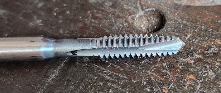
Make sure you're using a spiral "gun" tap.
(There was no disrespect intended, but hand tapping 96 holes at 4 minutes per hole is 6.4 hours! I was tapping at 300rpm. I don't know if that's an appropriate speed or not. But worked fine. WD40 as a lube. Plus I do have a brake resistor for my mill, and it stops pretty quickly.)