Surface Grinder Adapter Balancing Rings

thestelster

Ultra Member
Premium Member
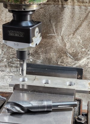
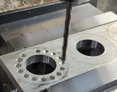
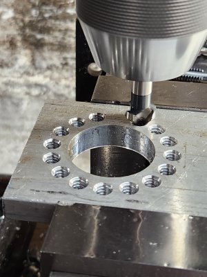
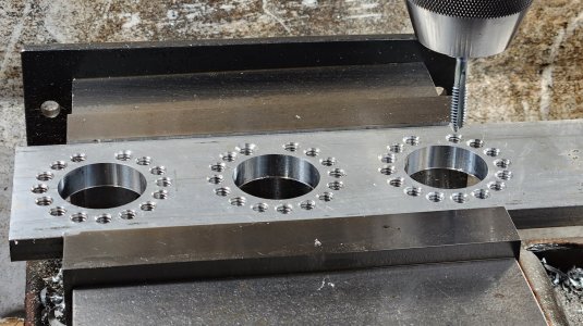
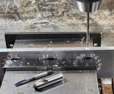
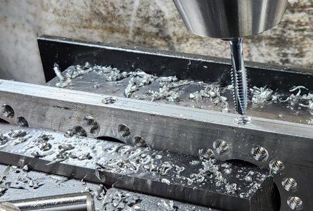
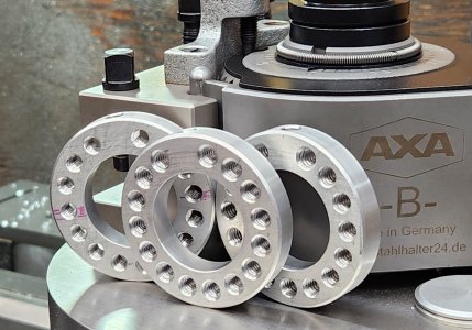
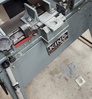
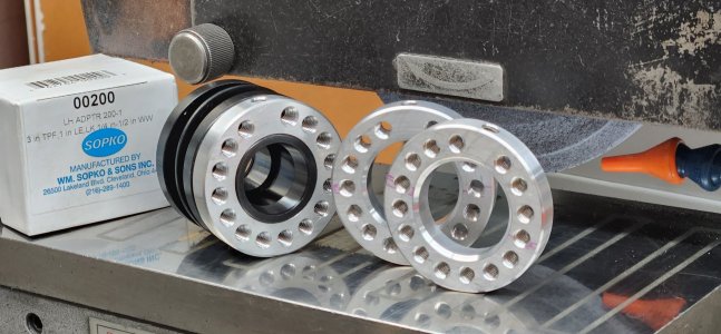
I made a balancing ring for my adapter a couple years ago. I only had one grinding wheel, so I only made one.

Well, I have another wheel now, and probably another one or two in the future. So I decided to make a few more rings.
 

Attachments

  • 20231017_153855.jpg
    20231017_153855.jpg
    767.9 KB · Views: 16
  • 20231017_160425.jpg
    20231017_160425.jpg
    363.2 KB · Views: 14
  • 20231017_181937.jpg
    20231017_181937.jpg
    381.6 KB · Views: 12
  • 20231017_184547.jpg
    20231017_184547.jpg
    352.1 KB · Views: 11
  • 20231018_111833.jpg
    20231018_111833.jpg
    435.9 KB · Views: 15

thestelster

Ultra Member
Premium Member
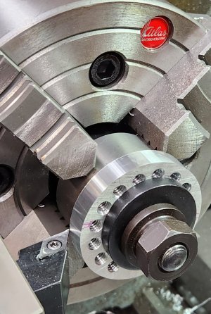
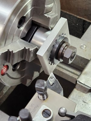
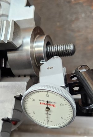
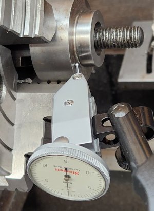
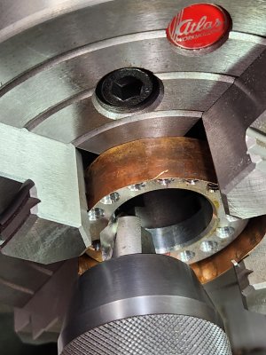
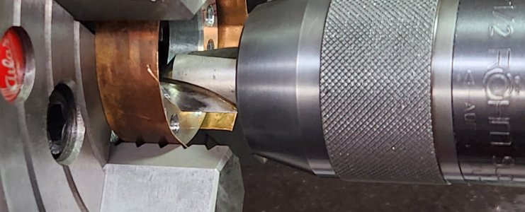
The adapters have a substantial rounded corner at the shoulder, so I need to make a chamfer deep enough so that the balancing ring sits flat against the back of the adapter.

The bored hole of the rings are 1.262", and I didn't have a chamfering tool large enough to do it during the milling session. So I had to improvise, by using a chamfering cutter gripped in the drill chuck which is mounted on the QCTP.
 

Attachments

  • 20231018_150614.jpg
    20231018_150614.jpg
    434.3 KB · Views: 15
  • 20231018_150635.jpg
    20231018_150635.jpg
    191.4 KB · Views: 15
  • 20231018_154021.jpg
    20231018_154021.jpg
    306.6 KB · Views: 14

jcdammeyer

John
Premium Member
I haven't figured out yet how they work as balancing rings for a grinder. I guess there will be more pictures?
 

thestelster

Ultra Member
Premium Member
I haven't figured out yet how they work as balancing rings for a grinder. I guess there will be more pictures?
Go to this site:


They have the description and methodology of their rings. I pretty well copied them.
 

jcdammeyer

John
Premium Member
Go to this site:


They have the description and methodology of their rings. I pretty well copied them.
Cool. Thank you for posting that. Has anyone tried that approach with bench grinder wheels?
 

thestelster

Ultra Member
Premium Member
Cool. Thank you for posting that. Has anyone tried that approach with bench grinder wheels?
On the surface grinder, you have an adapter that's bolted onto the wheel, and then the whole assembly bolted onto the spindle of the SG. That adapter cannot rotate about its axis otherwise you lose balance.

On a bench grinder its not set up for it. I mean yes, you could make an adapter of sorts that can work, as long as the wheel hole is larger than the grinder spindle. You would need to use steel for the balancing ring, and have it relieved in the center on one side, to act as the flange, and the same on the outboard flange. But then you might have to use thinner wheels depending on the lenth of the bench grinder spindle. Pretty complicated but doable? And I'm not sure you really need to do that for a bench grinder.
 

Susquatch

Ultra Member
Administrator
Moderator
Premium Member
Now to make round from square.

Very very nice Stel! I have to make a half dozen too! That's the same design I was aiming for. It's always way easier to learn from what someone else did.

I had a different Operation Order in mind. I had thought I would start with round bar instead of flat stock and then drill on my rotary table on the mill.

Why did you make them round last? Was that mostly so you could hold them in your vise during the drilling and tapping?

Perhaps I am missing something important that I wouldn't have discovered till I'd ruined a few parts or hit a dead end.
 

a smile

Lifelong hobby - cold iron
Premium Member
The adapters have a substantial rounded corner at the shoulder, so I need to make a chamfer deep enough so that the balancing ring sits flat against the back of the adapter.

The bored hole of the rings are 1.262", and I didn't have a chamfering tool large enough to do it during the milling session. So I had to improvise, by using a chamfering cutter gripped in the drill chuck which is mounted on the QCTP.
Forgive my stupidity, I have read it carefully for a long time and still can't understand how it works ------ need to insert large or small screws in its threaded holes to balance the center of gravity of the grinding wheel?
 

thestelster

Ultra Member
Premium Member
Very very nice Stel! I have to make a half dozen too! That's the same design I was aiming for. It's always way easier to learn from what someone else did.

I had a different Operation Order in mind. I had thought I would start with round bar instead of flat stock and then drill on my rotary table on the mill.

Why did you make them round last? Was that mostly so you could hold them in your vise during the drilling and tapping?

Perhaps I am missing something important that I wouldn't have discovered till I'd ruined a few parts or hit a dead end.
1. I didn't have round stock
2. There's 16 holes, so that's 22.5 degrees per hole....that's a pain doing it on the rotary table. Dividing head, yes.
3. All that swarf from drilling, threading, and boring all those holes, going into your chuck on the RT. Then having to clean it up to fo the next ring.
4. Parting can sometimes dish the surface.

I think doing it my way was very straight forward and pretty easy. If I had a large enough chamfering cutter to do the center bore would have saved me a lot of time.

On the first ring, I:
-spot drilled
-then directly to a #7 drill bit
-power tapped
-chamfered.
That means I went around 4 times.

The second and third rings, I spot drilled with a 1/2" 118° spot drill to a depth of 0.078". This way I didn't need to chamfer as a final operation, therefore only going around 3 times.
 
Last edited:

thestelster

Ultra Member
Premium Member
Forgive my stupidity, I have read it carefully for a long time and still can't understand how it works ------ need to insert large or small screws in its threaded holes to balance the center of gravity of the grinding wheel?
Yes. If you go to post #8 and follow the link, they explain it.

But, basically you put one screw at a time at directly opposite of the heavy side of the wheel.
 

thestelster

Ultra Member
Premium Member
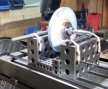
Unfortunately when I took this picture a couple years ago, I didn't show the other side with the balancing ring.

But when I balance the new wheel that I have, I'll show more pictures.
 

Attachments

  • 20211230_112330.jpg
    20211230_112330.jpg
    721.4 KB · Views: 12

Susquatch

Ultra Member
Administrator
Moderator
Premium Member
1. I didn't have round stock

I don't have flat stock.... LOL!

Truth is I'm still lathe centric and have not built up any significant stock for the mill yet. Maybe in 20 years......

Oh, wait..... I'll be 97 then.....better step that collection process up a bit!

2. There's 16 holes, so that's 2.25 degrees per hole....that's a pain doing it on the rotary table. Dividing head, yes.

Hadn't crossed that bridge yet and didn't know it was an issue waiting to bite me. I'll just make 18 holes 20 degrees apart. Instead of 16. If they get too close together I'll make the ring a bit bigger or use smaller set screws.

3. All that swarf from drilling, threading, and boring all those holes, going into your chuck on the RT. Then having to clean it up to fo the next ring.

Wasn't planning to use a chuck. Just an MT3 arbour in the center and maybe 4 Clamps as well as a backing board so I don't accidentally machine my table.

4. Parting can sometimes dish the surface.

Why is that an issue? I don't think it matters.

I think doing it my way was very straight forward and pretty easy. If I had a large enough chamfering cutter to do the center bore would have saved me a lot of time.

I don't disagree. There are always 42 different ways to do the same thing and if the end result is the same, they are all correct. In fact, I like your way just cuz it's not what I was planning to do. I always like seeing different ways of doing things.

On the first ring, I:
-spot drilled
-then directly to a #7 drill bit
-power tapped
-chamfered.
That means I went around 4 times.

Gotcha. But no power tapping on this farm.

The second and third rings, I spot drilled with a 1/2" 118° spot drill to a depth of 0.078". This way I didn't need to chamfer as a final operation, therefore only going around 3 times.

Faster! Always looking for better/faster/cheaper ways to do things is the mark of a true craftsman.
 

Susquatch

Ultra Member
Administrator
Moderator
Premium Member
Hey @thestelster.

Hopefully you can save me some cyphering.

Do you have dimensions or a drawing for your rings? And what size set screws are those?
 

Ian Moss

Well-Known Member
I don't do a lot of wheels, but I have had good luck by putting a patch of 5 min epoxy on the light side of the wheel. If that is still too light, it can extend it into an arc. Once over corrected, it can be teased back with a dremel tool with a sanding drum. Quick, cheap, infinitely adjustable and can be applied to both sides of the wheel. Dynamic balance can be different than static balance, so weighting both sides of the wheel may have a small advantage.
 

thestelster

Ultra Member
Premium Member
Hey @thestelster.

Hopefully you can save me some cyphering.

Do you have dimensions or a drawing for your rings? And what size set screws are those?
The set screws are 1/4"-20.
I'll get you the dimensions for the ring tomorrow. But basically, just used the dimensions off the Spoko 200- adapters that I have.

The ring thickness is 3/8" aluminium 6061.
 
Top