What do you mean, no power tapping? You're gonna die before you finish hand tapping 96 holes!!Gotcha. But no power tapping on this farm.
-
Scam Alert. Members are reminded to NOT send money to buy anything. Don't buy things remote and have it shipped - go get it yourself, pay in person, and take your equipment with you. Scammers have burned people on this forum. Urgency, secrecy, excuses, selling for friend, newish members, FUD, are RED FLAGS. A video conference call is not adequate assurance. Face to face interactions are required. Please report suspicions to the forum admins. Stay Safe - anyone can get scammed.
-
Several Regions have held meetups already, but others are being planned or are evaluating the interest. The Calgary Area Meetup is set for Saturday July 12th at 10am. The signup thread is here! Arbutus has also explored interest in a Fraser Valley meetup but it seems members either missed his thread or had other plans. Let him know if you are interested in a meetup later in the year by posting here! Slowpoke is trying to pull together an Ottawa area meetup later this summer. No date has been selected yet, so let him know if you are interested here! We are not aware of any other meetups being planned this year. If you are interested in doing something in your area, let everyone know and make it happen! Meetups are a great way to make new machining friends and get hands on help in your area. Don’t be shy, sign up and come, or plan your own meetup!
You are using an out of date browser. It may not display this or other websites correctly.
You should upgrade or use an alternative browser.
You should upgrade or use an alternative browser.
Surface Grinder Adapter Balancing Rings
- Thread starter thestelster
- Start date
A few years back, an enterprising hobbyist designed a 3D printed center of gravity apparatus that is one of the best devices to have compared to other prior methods. You put the model on the 4 pads, leading edge referenced to vertical pins. It then tells you CG position from that reference, accurate to a mm (and weight for convenience). Put a gram of ballast in the nose or tail, new CG is in recalculated instantly. Very important when you have to meet a specific CG limits. It has 2 cheapo digital fore/aft digital scales. Somehow he tapped into the board to obtain the 2 different weights & an Arduino program that solves the teeter-todder equation thus displaying results.
I mention this because I wonder if a digital balancer could similarly be made & cut down on the trial & error? Maybe if the shaft was supported in 2 discs like some balancers are, the discs could measure torque & direction & say 'put 5 grams at 224-deg position'... The End. Something like that?
 www.soaringusa.com
I mention this because I wonder if a digital balancer could similarly be made & cut down on the trial & error? Maybe if the shaft was supported in 2 discs like some balancers are, the discs could measure torque & direction & say 'put 5 grams at 224-deg position'... The End. Something like that?
SoaringUSA > Tools and Instruments > Center of Gravity Meter 3Kg
A precision digital CG and weight meter
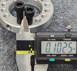
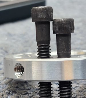
-OD: 2.230"Hey @thestelster.
Hopefully you can save me some cyphering.
Do you have dimensions or a drawing for your rings? And what size set screws are those?
-ID: 1.262"
-PCD of the holes is 1.750", or 0.875" from the center.
-Thickness: 3/8"
-Threaded holes: 1/4"-20
The balancing ring bore is about 1/2 thou' larger than the adapter boss.
Attachments
Last edited:
OD: 2.230"
ID: 1.262"
Thickness: 3/8"
Threaded holes: 1/4"-20
The balancing ring bore is about 1/2 thou' larger than the adapter boss.
Perfect Stel! Are the threaded holes drilled at the centerline of the ring or offset inward or outward?
Lastly, do you think 18 holes (20 degree intervals) will fit? Is there an issue with that waiting to bite me?
I mention this because I wonder if a digital balancer could similarly be made & cut down on the trial & error? Maybe if the shaft was supported in 2 discs like some balancers are, the discs could measure torque & direction & say 'put 5 grams at 224-deg position'... The End. Something like that?
This is an amazing idea.
But I confess I am pessimistic.
It's hard enough to get an electronic tire balancer to work properly where the weight difference is huge.
The best assessment I can offer is based on my reloading experience. I have tried a half dozen balance beam designs and at least as many electronic scales. They all SUCK when you approach 0.1 grain (approx 0.005 grams) resolution. To guarantee 0.1 resolution, your scale needs to be 0.01 resolution. Otherwise it could really be 0.2 or 0.0.
If you trust the output display of a digital scale, it's all good. But my testing shows conclusively that you cannot trust digital weighing systems. They all Lie.
In my quest for an accurate 0.01grain scale, I even bought a Gemology scale that claimed 0.01 grains and even came with a certificate . After extensive testing I concluded once again that: They all Lie.
All this is really just to say that I think the practicality of your idea requires an analysis of the required accuracy and an assessment of the credibility of available technology.
It's really really hard to beat a physical balance. They don't lie.
historicalarms
Ultra Member
Reading this tread has me "noodling" if a ball bearing track balancer that I described in jangers paint can shaker thread might not work.
You would downsize & simplify the bearing track to a simple groove in a disc the size you need. 1/8" balls prob all it would need and it would provide an instant re- balance every time you hit the start switch
You would downsize & simplify the bearing track to a simple groove in a disc the size you need. 1/8" balls prob all it would need and it would provide an instant re- balance every time you hit the start switch
I think this structure is easier to adjust the static balance, and relatively easy to make, the black balance block is bought online.
What holds the black blocks in place in the groove? I see the screw, but it's not obvious how the screw holds the block.
Reading this tread has me "noodling" if a ball bearing track balancer that I described in jangers paint can shaker thread might not work.
You would downsize & simplify the bearing track to a simple groove in a disc the size you need. 1/8" balls prob all it would need and it would provide an instant re- balance every time you hit the start switch
I wondered that too back when you posted it. The scale difference knocked it right out of my head.
Oh, the PCD of the holes is 1.750", or 0.875" from the center.Perfect Stel! Are the threaded holes drilled at the centerline of the ring or offset inward or outward?
Lastly, do you think 18 holes (20 degree intervals) will fit? Is there an issue with that waiting to bite me?
18 holes might be awfully close. You might need to get @PeterT to dimension it.
historicalarms
Ultra Member
That ring design in Smiles post is exactly what I envisioned would work but I would use loose balls instead of those locked tabs.
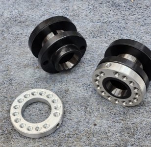
For reference, this is how Sopko themselves does it.

Both disk attach with a set screw at the heavy end and you balance by offsetting the two Disks as required. The cavities face each other so grinding dust doesn't accumulate.
From what I read, the kinetic precision system method is WAAAY easier to use.
Both disk attach with a set screw at the heavy end and you balance by offsetting the two Disks as required. The cavities face each other so grinding dust doesn't accumulate.
From what I read, the kinetic precision system method is WAAAY easier to use.
There are 2 styles of this type of balancer tab. The one above uses a pointy set screw and and ball bearing (sometimes a nylon ball) When the set screw is tightened, the ball is thrust 90 degrees toward the spindle, locking the tab. The other, older school version is a tapered threaded hole and split block. as the setscrew is tightened, it spreads the tab wider. both work very well.What holds the black blocks in place in the groove? I see the screw, but it's not obvious how the screw holds the block.
From what I read, the kinetic precision system method is WAAAY easier to use.
I've seen Bert take an hour and a half adjusting the tab type that @a smile uses. It may be a matter of technique,. I think the Sopco version can accommodate a much larger imbalance, but looks also a little fiddly. I'm willing to give the @thestelster version a whirl!
Oh, the PCD of the holes is 1.750", or 0.875" from the center.
18 holes might be awfully close. You might need to get @PeterT to dimension it.
Thanks Stel. If it was too tight, I'd prolly just switch to 3/16 set screws. I'd just do it if it were not for the fact that I'm a really big fan of 1/4-20 and 28. I think 1/4" is my favorite fastener size of all! Big enough that taps don't break so easy, lots of holding power, easy to align, compact size, easy to cut, easy to grind, etc etc etc.
If I had @PeterT 's Fusion 3D skills I'd whip that together myself. But I might need to do the old fashioned math instead.
Bolt circle is pie D = 3.14x1.75 = 5.5"
Spacing is 5.5 / 18 = 0.30
For 16 is 5.5 /16 = 0.34
It is tight but it will work. 20 degree intervals is compelling.
I don't do a lot of wheels, but I have had good luck by putting a patch of 5 min epoxy on the light side of the wheel.
I never replied to this Ian. Your approach is looking pretty attractive right about now.....
Mix up a small batch of steel reinforced JB Weld that is the weight of a few set screws. Gob it onto the wheel till its balanced lay the wheel down level with epoxy side up so the epoxy doesn't sag, and let it cure. Do any required fine tune on the other side later on as the wheel wears.
KISS!
Those numbers minus the diameter of the screw gives you the gap between. So for 18 holes of 1/4"-20 screws that's app. 0.050", which I guess is fine since there's no strength required for this application.Thanks Stel. If it was too tight, I'd prolly just switch to 3/16 set screws. I'd just do it if it were not for the fact that I'm a really big fan of 1/4-20 and 28. I think 1/4" is my favorite fastener size of all! Big enough that taps don't break so easy, lots of holding power, easy to align, compact size, easy to cut, easy to grind, etc etc etc.
If I had @PeterT 's Fusion 3D skills I'd whip that together myself. But I might need to do the old fashioned math instead.
Bolt circle is pie D = 3.14x1.75 = 5.5"
Spacing is 5.5 / 18 = 0.30
For 16 is 5.5 /16 = 0.34
It is tight but it will work. 20 degree intervals is compelling.
Attachments
Those numbers minus the diameter of the screw gives you the gap between. So for 18 holes of 1/4"-20 screws that's app. 0.050", which I guess is fine since there's no strength required for this application.
Ya sorry, I was just doing that part in my head. My bad.
0.050 is more than enough even if it did require significant strength.
Another point is that the screw thread doesn't need to be more than 20%. Power tapping suddenly looks far less scary!
Since I don't have a tapping head, I'd have to do it the old fashioned way and just let the threads pull the spindle with very light presssure, but it would solve the dilemma you mentioned about dying before I finish the job. (btw, that was mean!) LOL!