• Scam Alert. Members are reminded to NOT send money to buy anything. Don't buy things remote and have it shipped - go get it yourself, pay in person, and take your equipment with you. Scammers have burned people on this forum. Urgency, secrecy, excuses, selling for friend, newish members, FUD, are RED FLAGS. A video conference call is not adequate assurance. Face to face interactions are required. Please report suspicions to the forum admins. Stay Safe - anyone can get scammed.

Solid Toolpost Turret

What is the part number at MMC?

If you go to that link above, they have a whole wack of sizes. They offer cast iron in gray cast as well as ductile, but I'm pretty sure that grey cast has better dampening properties. I got the 8"D x 3.25" thick grey cast iron.
 
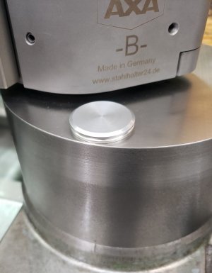
I just made a couple of aluminium plugs to block off swarf from getting into the countersink holes.
 

Attachments

  • 20221026_131235.jpg
    20221026_131235.jpg
    252.5 KB · Views: 2
That's one downside to the faceting operation, the counterbores would be exposed at an angle like my cad sketch. I'm sure there is still easy solutions though. I've seen plugs made with a little integrated stem to pull the plug out. Well you have a nice setup there, will be interested to hear how you like it in operation.
 
This is on my to do list too. My lathe is not so little and is probably just fine as is, but more is better when the operator isn't the best tool in the cabinet.

I mostly need help with parting. It's not that I can't part, it's just that it's almost never a painless activity, and I know I can do better so why not try. A dedicated parting plinth just seems so obvious so why not! @thestelster is my inspiration this time around, but @Dabbler has inspired me in the past. This project keeps moving up my priority list.

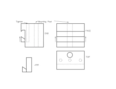
I'm thinking a plinth to replace the entire tool post with a dedicated 1" blade holder built right into it. At this time, the only real challenge is setting spindle center. Adjustments reduce rigidity, so I'd like to get around that somehow without losing the flexibility of being able to use various blades.
Lateral thinking? Centre height never changes, pull the clamp section up from underneath? Solid block, moving jaw from below, a slide or dovetail in the block. Project #42

Parting Tool Post.webp
 

If you go to that link above, they have a whole wack of sizes. They offer cast iron in gray cast as well as ductile, but I'm pretty sure that grey cast has better dampening properties. I got the 8"D x 3.25" thick grey cast iron.

Did the shipping slaughter you?
 
Lateral thinking? Centre height never changes, pull the clamp section up from underneath? Solid block, moving jaw from below, a slide or dovetail in the block. Project #42

View attachment 27444

Yes, exactly the kind of thinking I'm after. Allow me to add a few that might conflict with that though.

1. No good reason to have a vertical plinth. I'd prefer to make it curve down under the work to keep support as far forward as possible.

2. Same goes for L / R centering. I want to keep the blade over the middle of the cross-slide but yet leave room to clear the chuck and allow parting close to the Jaws.

3. I'd like a solid column under the blade. So I was thinking about a short fixed jaw on the front bottom and long rear top and moveable (tightening) jaws on the top front and bottom rear. Insert the blade on an angle and clamp the front top and rear bottom down.
 
Follow Up:

I've been using the solid tool post for a while now and quite like it. It's obviously more solid, I'm pretty sure there is less chatter during parting and boring, and it allows a little more elbow room.

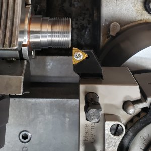
My biggest concern was threading without the compound slide. When threading in the past, I set the compound so its movement is parallel to the z-axis. All my threading tools are carbide inserts, non-topping, so that I can use the one insert to do many different pitches. But the tip of the insert has a radius of 0.003", so for fine threads it works well, but for coarser threads, once you've reached your radial infeed, you have to move the compound to widen the root of the thread for proper pitch diameter. But now without the compound, I either have to go deeper radially, giving you a very sharp root, which I don't want to do, or use full profile inserts, which will give you a perfect thread profile. But you need a different insert for each pitch. Well that's what I did today. I purchased a single full profile insert from KBC, (I usually buy Sandvik inserts, but you have to buy them in packs of 10, and at $40.00 each insert, I wasn't going to do that. Especially if I have to but packs of 10 for every pitch!!)

The thread I needed to cut is 1.0625 x 16tpi UN60°. According to the Sandvik catalog, the radial infeed is 0.041". But it also tells you to have the major diameter of the tread 0.004" larger, because the insert will clean up the crest. I turned my part to 1.066", and started to thread and crept up to that depth of cut and perfecto! And the OD of the part is 1.062" and absolutely perfect fit.

So now I've addressed this issue in regards to disadvantages of a solid compound, and I'm happy with the outcome.
 

Attachments

  • 20221127_133302.jpg
    20221127_133302.jpg
    279.8 KB · Views: 23
I've been using the solid tool post for a while now and quite like it. It's obviously more solid, I'm pretty sure there is less chatter during parting and boring, and it allows a little more elbow room.

What's with the Philips screw in the insert?

Visually, the insert looks too small for that 16 TPI thread. Obviously an illusion as the thread looks great!

Did you use your new thread mic for this? You explained how you did the thread so I know it wouldn't have been for guidance - just wondering if you tried it for sh&ts & giggles. Or is the 16tpi anvil one of those that is missing?
Haha, well here is the story about the screw. My Sandvik threading tool utilizes a Quick Change system for swapping out inserts. No need to remove the screw, just back it out 1 turn, and the insert comes out, put new insert in and tighten. Very slick and you don't drop those fricking tiny screws into the swarf mess underneath. So the Sandvik inserts actually have a larger countersunk hole. When I ordered the full profile insert from KBC, it's insert hole is standard dimension, so the Sandvik screw wouldn't fit. That Philips screw was the only flat head screw I had that was M4 thread, and that was long enough to thread into the tool. The insert registers against the pocket sides, so it's quite solid.

My thread mikes are only up to 1", so wouldn't work. And yes, I do not have that anvil for the Mitutoyo. I should be ordering a couple sets this week.
 
My thread mikes are only up to 1", so wouldn't work. And yes, I do not have that anvil for the Mitutoyo. I should be ordering a couple sets this week.
When I was lusting over used Mitutoyo thread mic (and maybe thankfully gave up) I noticed so many kits were missing anvils, which is a real PITA. Sometimes you see anvils sold separately on Ebay, but often not cheap either. I suspect the offshore anvils don't fit, they look quite different.

 
Pardon my probably ignorant questions. I take it that these inserts are meant for plunge cutting rather than along the thread flank like you would do with a HSS or more standard tool bit?

The reason I ask is way back when I was writing code for my ELS there were people that did not have a compound slide and plunge cutting threads produced awful results but with only gears and HSS tool bits there wasn't much of a choice.

So what I did was simulate the compound slide. After all if you move the carriage over a tad and the cross slide in a tad the tip of the tool bit moves along the hypotenuse of the angle created by the two distances. Choose the values correctly and it can be 29.5 degrees just like you'd set up the compound.

All the software does is change the starting position relative to the spindle and in effect the thread starts a little bit further than it did before. And move the cross slide in and you have that 29.5 degree angle. Pretty sure LinuxCNC and MACH and other CNC systems do it the same way since they don't control the compound at all.

These tool bits seem like the cats meow for plunge threading starting at exactly the same sport especially if then then shave the crest of the thread so the total depth is perfect.
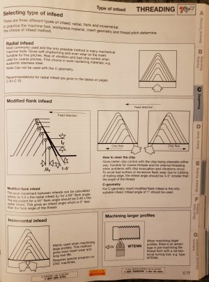
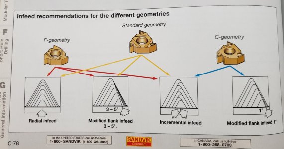
Yes, the Sandvik resources suggests that the inserts can be used in several methods:

radial infeed, what I do; modified flank infeed, (coming in up to several degrees less 30°); and incremental infeed (alternating going in from the leading edge and following edge). And I guess, that's the beauty about CNC!!
 

Attachments

  • 20221127_192146.jpg
    20221127_192146.jpg
    392.5 KB · Views: 13
  • 20221127_192816.jpg
    20221127_192816.jpg
    214.5 KB · Views: 14
Yes, the Sandvik resources suggests that the inserts can be used in several methods:

I didn't realize that there were so many variations out there. I've only ever heard of plunge and 29.x to 30. This is very cool info.

I also like the graphics sandvik provides. I wish I had seen that before all my years of trying to explain the 29.x method.
 
Fascinating. I'll have to add the Radial in-feed approach as a threading parameter to the next version of the ELS code. Although I guess if you have CNC you don't really need it. But I like the idea of the pitch sized tool bit ensuring depth radius and crest height are correct.

Odds are though, I'd probably chip the cutter the first time I try it.:(
 
I finished making my own like a week ago. Works great! It makes my lathe way more stable. Its not just for parting but other work as well! I show a picture but essentially it is a 5" block of steel that is few inches high and has a T milled in for the Aloris tool post. I used 4 bolts to hold it vs. original 2.
So far no major issues with not having a cross slide.

I am now machining a widget I saw here - to hold a large round rod and be able to make it square or hex with ease. Using 7" x 2" round block that I make into 5.5 in or so square with a 2.5" hole. Going max size I can go.

Pictures????
 
Before, while contemplating whether the advantages surpassed the disadvantages of a solid tool post, my main concerns where: threading, medium length tapers, and steep tapers. All of which makes the compound slide so versatile. I addressed the medium length tapers ( up to about 12°) by using my taper turning attachment. Though there are some issues we have to look at, in regards to advancing in the x-axis.

The threading has been solved by using full-form thread inserts. Though there is the added expense of having a different insert for each thread pitch I want to cut.

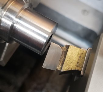
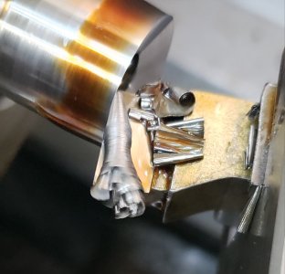
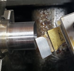
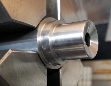
The final piece of the puzzle was short steep tapers. And today I addressed this by modifying a cemented carbide cutter, and using it as a form tool. I often have to machine an 11° crown (concave cone) at the end of a rifle barrel. Simple enough to do with the compound, but with a solid tool post, not as easy. In this case I positioned the Multifix tool holder over 2 positions, which gives me 18° (if 18° works, so will 11°, and this was just a test). I will need to make a 2° shim and put it next to the cutter to get me the extra angle.

Was going to a solid tool post worth all the effort and added expense, and not achieving 100% similar capabilities of the compound in regards to the three criteria I was concerned with? Probably not, but I'll keep it like this for a long while and see if it doesn't frustrate enough to change back.
 

Attachments

  • 20221129_181744.jpg
    20221129_181744.jpg
    310.1 KB · Views: 10
  • 20221129_181715.jpg
    20221129_181715.jpg
    343.3 KB · Views: 10
  • 20221129_181652.jpg
    20221129_181652.jpg
    300.8 KB · Views: 10
  • 20221129_183410.jpg
    20221129_183410.jpg
    258.5 KB · Views: 11
The final piece of the puzzle was short steep tapers. And today I addressed this by modifying a cemented carbide cutter, and using it as a form tool. I often have to machine an 11° crown (concave cone) at the end of a rifle barrel. Simple enough to do with the compound, but with a solid tool post, not as easy. In this case I positioned the Multifix tool holder over 2 positions, which gives me 18° (if 18° works, so will 11°, and this was just a test). I will need to make a 2° shim and put it next to the cutter to get me the extra angle.

That's a pretty wide cut to do all at once... What are you gunna do when it's a bull barrel and a 17 caliber hole?

I know, nobody is ever gunna want that, it's only worst case. But there will be a few who want a 224 hole in a bull barrel.
 
Back
Top