-
Scam Alert. Members are reminded to NOT send money to buy anything. Don't buy things remote and have it shipped - go get it yourself, pay in person, and take your equipment with you. Scammers have burned people on this forum. Urgency, secrecy, excuses, selling for friend, newish members, FUD, are RED FLAGS. A video conference call is not adequate assurance. Face to face interactions are required. Please report suspicions to the forum admins. Stay Safe - anyone can get scammed.
-
Several Regions have held meetups already, but others are being planned or are evaluating the interest. The Calgary Area Meetup is set for Saturday July 12th at 10am. The signup thread is here! Arbutus has also explored interest in a Fraser Valley meetup but it seems members either missed his thread or had other plans. Let him know if you are interested in a meetup later in the year by posting here! Slowpoke is trying to pull together an Ottawa area meetup later this summer. No date has been selected yet, so let him know if you are interested here! We are not aware of any other meetups being planned this year. If you are interested in doing something in your area, let everyone know and make it happen! Meetups are a great way to make new machining friends and get hands on help in your area. Don’t be shy, sign up and come, or plan your own meetup!
You are using an out of date browser. It may not display this or other websites correctly.
You should upgrade or use an alternative browser.
You should upgrade or use an alternative browser.
Show us your Tool Height Standard
- Thread starter YYCHM
- Start date
For the lathe? I use the old fashioned approach of pushing a straight piece of metal up against the work and looking to see if it's vertical. I adjust up or down until it is.It's time for me to make one, but before I do, I want to see what you guys use.
Craig
For the mill I haven't yet arrived at a tool height setter. I tend to move the tool closer until a piece of paper is grabbed. Measure the paper and tweak it that much closer. So far nothing I've done requires anything better.
I did try to buy one from China but that fell through. Should really try again.
@jcdammeyer The way you are used to works, and fairly well. I leaned to use a standard, which is very fast, and much more accurate....
Here's mine on my 12" lathe:

Here's mine on my 12" lathe:
Last edited:
It might be my own interpretation of hobby lathe history but I think when people were putting cutters into non-repeatable tool posts & diddling with shims or tool angle in the lantern style posts, it made sense to have an independent gage or standard to check the tool tip against independently to avoid disturbing a part in progress. But seems like most everyone has a dovetail tool post these days & a small collection of inexpensive knockoff holders. What I find quickest with a new tool is just turn the end of a scrap bar & adjust height until the nib is gone. Usually (ideally) once set, the height should remain that way with other tool changes.
I use to have a 'standard' which was just a bar turned to match my center height. Then I just used DTI on Noga type mag base to reference that height like you would on a surface plate & compare to tool height using the lathe bed datum. This was quite accurate especially on more steeply angled tool edges because you are measuring the very extremity of the point. Having said this, I have tweaked some cutting tools up or down a smidgen if it decides it likes to cut better there. Tool height setting to 0.001' doesn't factor when the tool is loaded, things can bend & deflect a bit. The suspended ruler method is quick & dirty but I've also seem some so-so inserts that have quite rounded profiles in side view & can get tricked by this method.
I use to have a 'standard' which was just a bar turned to match my center height. Then I just used DTI on Noga type mag base to reference that height like you would on a surface plate & compare to tool height using the lathe bed datum. This was quite accurate especially on more steeply angled tool edges because you are measuring the very extremity of the point. Having said this, I have tweaked some cutting tools up or down a smidgen if it decides it likes to cut better there. Tool height setting to 0.001' doesn't factor when the tool is loaded, things can bend & deflect a bit. The suspended ruler method is quick & dirty but I've also seem some so-so inserts that have quite rounded profiles in side view & can get tricked by this method.
I'm a standard user Craig. Lightning fast, super convenient, and plenty accurate enough. Takes 3 seconds to check height and a few more to adjust if needed. Can't imagine taking cuts or using a ruler or comparing to a center ever again.
Like so many things in my shop, my standard is turned from an old bolt. This provided the opportunity to turn the head of the bolt down to create a bigger base that was more stable on my ways. It is recessed on the bottom so it's easy to make sure it isn't sitting on a film of oil or any scarf.
The standard has a sharpie mark on it. This is not to index the standard. It's only there to provide a visual contrast.
I use my eyes first and then my finger and then my fingernail to gauge height difference between the tool and the standard.
The two photos are the same with different focusses - one for each end.
For the lathe? I use the old fashioned approach of pushing a straight piece of metal up against the work and looking to see if it's vertical. I adjust up or down until it is.
For the mill I haven't yet arrived at a tool height setter. I tend to move the tool closer until a piece of paper is grabbed. Measure the paper and tweak it that much closer. So far nothing I've done requires anything better.
I did try to buy one from China but that fell through. Should really try again.
You should make a standard for your lathe. You will never regret it.
I'm not thrilled with adjusting height on my mill yet at all. Taking a dust cut isn't very cool. In fact, it downright sucks.
I haven't mastered the paper technique yet.
An edge finder is awesome for x & y, but sucks for Z.
I'm open to suggestions and any other method that might work. PLEASE come back here and post anything you find that actually works.
VicHobbyGuy
Ultra Member
I made this from a bolt in my scraps box before I realized how expensive brass is nowadays! ")

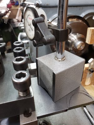
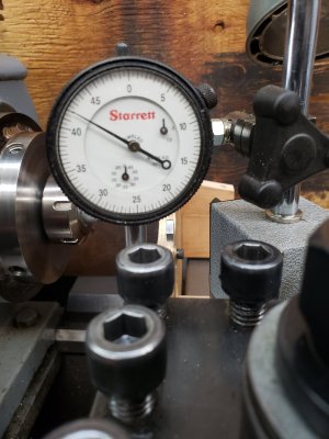
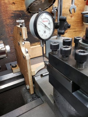
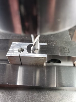
For the lathe, I have a dedicated dial indicator with a pin point tip. It takes a little while in the beginning to set up the exact height to center, but you do it once, and you're good as golden, unless you drop it. You just move the indicator tip to the cutting edge. If its too low, I shim it up by that amount. You can see in the photos, that the cutting edge is 0.008" low of center, so I'll put an 0.008" shim underneath the tool.
Attachments
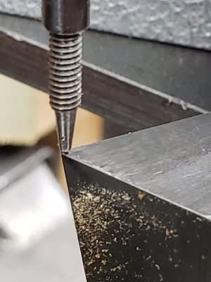
For the milling machine, x and y axis, I use the Starrett edge finder. In Z-axis, raise the column until the endmill is close 1/8" away from touching and lock the column. Move the cutter away for the piece, unlock the quill, and move it up and down a couple times to free it up.
Move the endmill to your part, put a feeler gauge on top of your part, lower the quill until it touches. Lock the quill, move off the part, let the endmill drag the feeler gauge off. Lower the quill, or raise the column by the thickness of your feeler gauge.
Move the endmill to your part, put a feeler gauge on top of your part, lower the quill until it touches. Lock the quill, move off the part, let the endmill drag the feeler gauge off. Lower the quill, or raise the column by the thickness of your feeler gauge.
Attachments
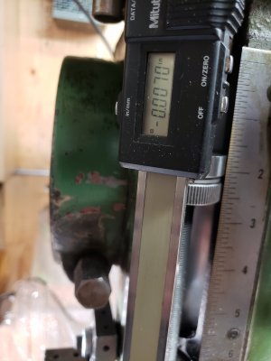
For the lathe, I have a dedicated dial indicator with a pin point tip. It takes a little while in the beginning to set up the exact height to center, but you do it once, and you're good as golden, unless you drop it. You just move the indicator tip to the cutting edge. If its too low, I shim it up by that amount. You can see in the photos, that the cutting edge is 0.008" low of center, so I'll put an 0.008" shim underneath the tool.
I think for your situation with a tool post like yours, that's the way to go. By measuring, yo u know exactly what size shim to use
With a piston or wedge type tool post, it isn't necessary. We lucky B's can just turn a knurled nut to dial it in using a standard. No measurements needed.
It might be my own interpretation of hobby lathe history but I think when people were putting cutters into non-repeatable tool posts & diddling with shims or tool angle in the lantern style posts, it made sense to have an independent gage or standard to check the tool tip against independently to avoid disturbing a part in progress. But seems like most everyone has a dovetail tool post these days & a small collection of inexpensive knockoff holders. What I find quickest with a new tool is just turn the end of a scrap bar & adjust height until the nib is gone. Usually (ideally) once set, the height should remain that way with other tool changes.
I use to have a 'standard' which was just a bar turned to match my center height. Then I just used DTI on Noga type mag base to reference that height like you would on a surface plate & compare to tool height using the lathe bed datum. This was quite accurate especially on more steeply angled tool edges because you are measuring the very extremity of the point. Having said this, I have tweaked some cutting tools up or down a smidgen if it decides it likes to cut better there. Tool height setting to 0.001' doesn't factor when the tool is loaded, things can bend & deflect a bit. The suspended ruler method is quick & dirty but I've also seem some so-so inserts that have quite rounded profiles in side view & can get tricked by this method.
I dunno Peter. I think the old hardware and especially the ones like @thestelster has benefit from measuring things and then selecting the right shim.
My first lathe was a lantern style tool post. I think a standard might have worked if there was something to set it on. Mine had two V rails. You couldn't use a standard. Even the top of the cross-slide wasn't flat. There may be some out there though. I don't know.
Regardless, I believe you are missing out by not using a standard. You need to make one and try it. I'll wager a coffee you will wonder how you ever got along without it. I like my coffee double cream.....
")
If I've done it right this link should point to a short video, hand held cell phone, of my CNC router doing homing. It's a short script in MACH3 that moves down until the contact is made. It then adds 0.062" (PC board thickness) to that point and sets that as 0.000" for the Z axis.
I can set up the big camera on a tripod along with some lights and do a better job if someone wants.
And this is how I find the edges now on the mill with LinuxCNC.
I can set up the big camera on a tripod along with some lights and do a better job if someone wants.
And this is how I find the edges now on the mill with LinuxCNC.
For the milling machine, x and y axis, I use the Starrett edge finder. In Z-axis, raise the column until the endmill is close 1/8" away from touching and lock the column. Move the cutter away for the piece, unlock the quill, and move it up and down a couple times to free it up.
Move the endmill to your part, put a feeler gauge on top of your part, lower the quill until it touches. Lock the quill, move off the part, let the endmill drag the feeler gauge off. Lower the quill, or raise the column by the thickness of your feeler gauge.
I like this. I will have to try it. I have a set of feeler gauges that I had to use as shims and have a lot of them left that I could use for this task.
Did you ever measure how much the end mill digs into the feeler gauge when you this? Or is that my job since I'm wondering about it.......

Ive been wondering about an electronic method that works the same way with an insulated pad on the part connected to an E-box with a sort of continuity tester in it.
If I've done it right this link should point to a short video, hand held cell phone, of my CNC router doing homing. It's a short script in MACH3 that moves down until the contact is made. It then adds 0.062" (PC board thickness) to that point and sets that as 0.000" for the Z axis.
I can set up the big camera on a tripod along with some lights and do a better job if someone wants.
And this is how I find the edges now on the mill with LinuxCNC.
Your videos are just fine as is John.
Thank you!
Thanks.Your videos are just fine as is John.
Thank you!
Here's the script for MACH3. It sets the Z position to 0.0625" which is the PC board height above where it's sitting. I named it "TouchPlateButton.ms1 and it's linked to the set tool zero button. The signal #22 is the 'probe' input which in ports and pins is Port 2 pin 11.
response = MsgBox( "Auto Zeroing, Put Ground Clip on Tool bit", 1 )
If IsSuchSignal (22) Then
code "G31 Z-3 F20"
While IsMoving()
Wend
Call SetDRO( 2, 0.0625 )
code "G1 Z1"
While IsMoving()
Wend
response = MsgBox( "Auto Zeroing Complete. Remove Ground Clip", 1 )
End If
@Dabbler sent me these.... THANKS!
I love the way @Dabbler thinks, but man I hate YouTube. I fell asleep watching these videos. I really HATE the way videos like these take forever to show one minute of good content. I set the ox tools one going and it's been playing in the background while I did a lot of other things including writing this message ... Ugh.....
Compare that with what @jcdammeyer provided earlier. In much less than a minute you have what you want.
Sorry for the anti you tube rant.
I think what's important for making a good standard is to use two gauge pins to make the standard. So you know the standard is the right height.
So......., I felt so bad dishing the videos above that I decided to find one too. Ya, just looking was plenty painful painful painful punishment for my bad attitude.....
I don't like Joe Pie any more than any other you tuber. But at least this particular video on this subject is mercifully shorter and also shows how to achieve the center height on the standard. When I made mine I used the same method but didn't use gauge pins (mostly cuz I don't have any). I used a quarter inch end mill and turned a half inch rod in the lathe and measured with a micrometer so I could be sure my center was truly centered.
Former Member
Guest
Standards are exactly that. A standard. Accuracy is based on how they are used in some cases do not matter on what infinite decimal accuracy they are made or not made but in how consistently they are used.
In most cases the best accuracy is based on the simplest standards with the easiest repeatable method.
So for me a measurement of fixed point on the lathe for tool height gives a consistent tool height.
On the mill I use vellum paper (as thickness is very predicatable and consistent). My cnc does only manual tool changes so recalibration is best at each tool change for ht only. For x&y I use conductive probe or tool with paper for the initial set up, both take about the same time.
If I don't want to use paper, I use Dykem and touch to scrape bare with tool, generally slow but you can achieve into the 1/10's accuracy.
Last one I love, is center on a round, simple ruler to level and you are centered.
The feeler gauges are hardened, and you only use light pressure to touch off, so no digging in. Do a test. Machine a piece of aluminium flat, then using the same set up, move off, and try my method.I like this. I will have to try it. I have a set of feeler gauges that I had to use as shims and have a lot of them left that I could use for this task.
Did you ever measure how much the end mill digs into the feeler gauge when you this? Or is that my job since I'm wondering about it.......
Ive been wondering about an electronic method that works the same way with an insulated pad on the part connected to an E-box with a sort of continuity tester in it.
The feeler gauges are hardened, and you only use light pressure to touch off, so no digging in. Do a test. Machine a piece of aluminium flat, then using the same set up, move off, and try my method.
Sounds like a plan!