Last year I tried to buy one of these but the Chinese store cancelled the order. I was refunded but never did try again.
https://www.aliexpress.com/item/4000480545163.html
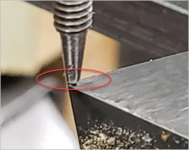
With these you can load a tool, move over and go down until contact is made. No clip lead needed on the tool. As long as you know the height of the sensor assembly you can then enter the tool length into the tool table for either MACH or LinuxCNC. However, it doesn't help with finding the top of the work say mounted in the vise.
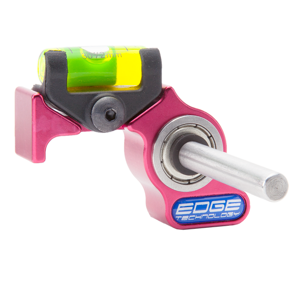
Tormach also sells a holder along with a gauge so you can measure the distance from the TT Reference surface to a tool tip. Then you can enter that in relative to the quill.
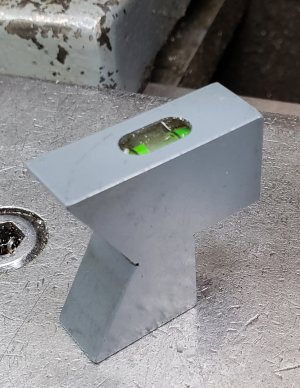
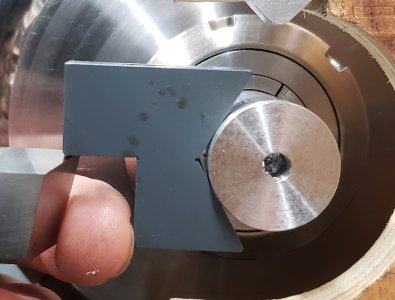
I think I'd rather have the sensor mounted on the table so that I can put a drill bit into a chuck, zoom over and touch off to find the length of the now mounted drill. That length is then used to properly drill holes to depth.
https://www.aliexpress.com/item/4000480545163.html
With these you can load a tool, move over and go down until contact is made. No clip lead needed on the tool. As long as you know the height of the sensor assembly you can then enter the tool length into the tool table for either MACH or LinuxCNC. However, it doesn't help with finding the top of the work say mounted in the vise.
Tormach also sells a holder along with a gauge so you can measure the distance from the TT Reference surface to a tool tip. Then you can enter that in relative to the quill.
I think I'd rather have the sensor mounted on the table so that I can put a drill bit into a chuck, zoom over and touch off to find the length of the now mounted drill. That length is then used to properly drill holes to depth.