• Scam Alert. Members are reminded to NOT send money to buy anything. Don't buy things remote and have it shipped - go get it yourself, pay in person, and take your equipment with you. Scammers have burned people on this forum. Urgency, secrecy, excuses, selling for friend, newish members, FUD, are RED FLAGS. A video conference call is not adequate assurance. Face to face interactions are required. Please report suspicions to the forum admins. Stay Safe - anyone can get scammed.

Schematics and Circuit Board layout with Fusion 360

This is the update post I've been hoping to see one of these days before disrupting my other actual and intended projects with this one....

But "E117-01 Schematic" is the one the pins need to match, yes? And there are only 15 pins that matter?

The ESP pinout is identical for E117-00, and E117-01

Only 10 I/O pins are actually used (unless you're using iGaging scales)

E117-01 changes:
+ Option for differential inputs (also supports single ended)
+ Uses an appropriate input buffer instead of the kludgy part specified on TDRO website
+ Dual dip spacing for narrow or wide ESP board
+ Board is smaller
+ Uses less and larger components to ease hand soldering
- Does not support the iGaging scales with the proprietary interface
 
Last edited:
There are some ways around the different esp32 boards but they can get messy. I have used 24awg wire and wired pin to pin to make a board fit. It’s not pretty but does work, the hardest part really is programming the esp32 the rest is just soldering wires.
Another work around that is a little more elegant is to order an "expansion" board.

Screenshot 2025-05-24 at 10.04.00 AM.png

Again, you need to make sure it will fit the ESP 32 you are getting. Then just a matter of connecting the wires to the board and soldering them into the PCB in the appropriate place.
 
E117-01 are the boards I got made.

As for esp32's people can buy them directly from Yurhi and they come programmed.
I am looking at getting some 38 pin esp32's off amazon, and then will compare the pinout's to the ones needed for the boards. When I get them I will post if they will work or not.

I have 10 of the boards here. I will be honest with everyone. I will not likely be able to test these until the fall. I will send boards to any wanting some. With the postal strike up and downs, I am not sure if and when we can get them to people. But I will get them in the mail as soon as possible for those that want them.
 
E117-01 are the boards I got made.

I have 10 of the boards here. I will be honest with everyone. I will not likely be able to test these until the fall. I will send boards to any wanting some. With the postal strike up and downs, I am not sure if and when we can get them to people. But I will get them in the mail as soon as possible for those that want them.
Please send one to me and I will test it.
 
These are the 38 pin esp32 boards I got off amazon, I am not sure if they will pin for pin work yet. But I think all the power pins are good. If someone else can have a look as well or help in confirming. These esp32 did not have a pinout on them other then the one printed on the bottom. They do easily fit the boards we had made.
 
Update September 6, 2025
Hi,

Summer vacation is over, so I spent an hour populating and testing one of the E117-01 boards that I described.

If anyone is interested in reproducing, the manufacturing files are attached.

Notes:
0) See notes on the schematic.
1) This works with conventional magnetic and glass scales, it does not work with igaging type scales.
2) If you use 4-40 nuts to mate with the DB-9 connectors, place a Fiber washer under each nut on the top side as shown.
3) I'm not sure what version of firmware is on the ESP boards as it was provided by Tom.
4) IIRC some features perhaps the tach (I'm not sure) are disabled with the free firmware, I tested the X, Y Z.
5) djberta might have spare boards?

Moderator Edit - All obsolete files deleted to avoid confusion at OP's request
 
Last edited by a moderator:
I have a couple of the boards from @djberta (thanks again!) , but have not yet acquired all the bits and pieces to populate them, only the ESP boards. I don't have any scales. When I get them I may want to bring them for a quick test to someone here on the island who doesn't mind me trying them on their scales before I get scales of my own.
 
I have a couple of the boards from @djberta (thanks again!) , but have not yet acquired all the bits and pieces to populate them, only the ESP boards. I don't have any scales. When I get them I may want to bring them for a quick test to someone here on the island who doesn't mind me trying them on their scales before I get scales of my own.
Depending on when you would be coming up (I'm away a fair bit in the next month) you are welcome to try them out on one of my machines.
 
Depending on when you would be coming up (I'm away a fair bit in the next month) you are welcome to try them out on one of my machines.
Gotta put 'em together first, and "stuff" keeps getting in the way - but thanks!
 
Looking at the docs on the Touch DRO site and then at the schematic E117-01, I realized (Duh!) that since the free version of the firmware does not include the touch or tach functions, that all of the following parts should be able to be left out, with no reduction in capability:

TB2, TB3,
U2
R1, R2
C5, C19, C11

And of course if you are supplying power via the USB port, TB1, C1 and C2 are also not needed.
I did briefly wonder if those unused inputs had to be held high or low, but since they are presumably ignored by the free version of the firmware, and since there are many other unused I/O pins that are left to float, I'm thinking not. But I will study the data sheet.

As far as I could tell there is (understandably) no option to purchase just the code with the complete functionality of the commercial product.
 
Looking at the docs on the Touch DRO site and then at the schematic E117-01, I realized (Duh!) that since the free version of the firmware does not include the touch or tach functions, that all of the following parts should be able to be left out, with no reduction in capability:

TB2, TB3,
U2
R1, R2
C5, C19, C11

And of course if you are supplying power via the USB port, TB1, C1 and C2 are also not needed.
I did briefly wonder if those unused inputs had to be held high or low, but since they are presumably ignored by the free version of the firmware, and since there are many other unused I/O pins that are left to float, I'm thinking not. But I will study the data sheet.

As far as I could tell there is (understandably) no option to purchase just the code with the complete functionality of the commercial product.
Agreed on TB2, TB3 assuming you don't have the full featured firmware.

Who knows if the internal pull-ups are enabled for pins 3, 4?
+ So to be on the safe side I would populate U2, R1, R2

Even if you're powering via the USB Connector, I would also populate C1, C2 because some decoupling near that ESP module would be a good idea.
 
Update:

Now that I can flash ESP32 modules easily, I learned a little bit about the various versions of hardware and firmware. See this thread for details:
https://canadianhobbymetalworkers.com/threads/touch-dro-esp-flashing.15084/post-229574

So to that end I tweaked the PCB so that you can use either the old or new versions of the firmware, via a few jumpers. The previous board will not work as is with the latest firmware.

Files attached if anyone prefers to save the hassle of making a proto-board solution. I really detest doing proto-board builds, they always take way longer than expected. The files attached can be sent to PCBWay or AllPCB and you can usually get a batch of boards for $5 plus shipping. It takes about a week to your door.

Just be aware that this is for personal hobby use only and can't be sold/advertised/used professionally etc.

Rules from TouchDRO:

"You can develop your own PCB and use it with TouchDRO. I'm perfectly OK with that.

I'm very much not OK with anyone who develops "their own PCB", loads my firmware and starts selling them."

--------------------------------------------------------------------------------------------------------------------------------------------

Results of firmware testing....

I tested three versions of the firmware:
a) Unidentified version that was already on the ESP32 that Tom sent
b) V1.6
c) V3.2 (touchdro-free-v3.2.zip)

Unidentified version possibly V1.4?
- tested previously on a -01 board with 5 micron single ended scale, tested okay.
- with 1 micron scales gives errors when moving fast in reverse direction.
- My hunch (pure speculation) is that this version uses X1 style quadrature decoding that is prone to this type of error.

Version V1.6 (free from DIY page)
Did not test with 5 micron scales, but with 1 micron scales behaves just like the unidentified version.

Version V3.2 (touchdro-free-v3.2.zip) free from DIY page
Did not test with 5 micron scales, expect it will be fine based om 1 micron testing.
Tested with single ended (TTL) 1 micron scale, works fine with E117-02 circuit, with jumpers set for V3.x firmware
Works fine with 1 micron scales can move at rapid speed 120 IPM,in either direction.

The E117-02a circuit below also has improved noise immunity when using single ended (TTL) type scales.


Moderator please delete the post immediately before this (213) as this post supersedes that information.

Moderator - Done.

 

Attachments

Last edited by a moderator:
Update:

Now that I can flash ESP32 modules easily, I learned a little bit about the various versions of hardware and firmware. See this thread for details:
https://canadianhobbymetalworkers.com/threads/touch-dro-esp-flashing.15084/post-229574

So to that end I tweaked the PCB so that you can use either the old or new versions of the firmware, via a few jumpers. The previous board will not work as is with the latest firmware.

Files attached if anyone prefers to save the hassle of making a proto-board solution. I really detest doing proto-board builds, they always take way longer than expected. The files attached can be sent to PCBWay or AllPCB and you can usually get a batch of boards for $5 plus shipping. It takes about a week to your door.

Just be aware that this is for personal hobby use only and can't be sold/advertised/used professionally etc.

Rules from TouchDRO:

"You can develop your own PCB and use it with TouchDRO. I'm perfectly OK with that.

I'm very much not OK with anyone who develops "their own PCB", loads my firmware and starts selling them."

--------------------------------------------------------------------------------------------------------------------------------------------

Results of firmware testing....

I tested three versions of the firmware:
a) Unidentified version that was already on the ESP32 that Tom sent
b) V1.6
c) V3.2 (touchdro-free-v3.2.zip)

Unidentified version possibly V1.4?
- tested previously on a -01 board with 5 micron single ended scale, tested okay.
- with 1 micron scales gives errors when moving fast in reverse direction.
- My hunch (pure speculation) is that this version uses X1 style quadrature decoding that is prone to this type of error.

Version V1.6 (free from DIY page)
Did not test with 5 micron scales, but with 1 micron scales behaves just like the unidentified version.

Version V3.2 (touchdro-free-v3.2.zip) free from DIY page
Did not test with 5 micron scales, expect it will be fine based om 1 micron testing.
Tested with single ended (TTL) 1 micron scale, works fine with E117-02 circuit, with jumpers set for V3.x firmware
Works fine with 1 micron scales can move at rapid speed 120 IPM,in either direction.

The E117-02a circuit below also has improved noise immunity when using single ended (TTL) type scales.


Moderator please delete the post immediately before this (213) as this post supersedes that information.
Thanks for the extra work you put into this!

I'm going to update my firmware to 3.2 based on your testing.
 
Thanks for the extra work you put into this!

I'm going to update my firmware to 3.2 based on your testing.

Tom,

You will need to move the connections that go to the ESP32 (see details in the schematic E117-02a) before using the new firmware.

You can probably just jumper the pins with say a 3k9 resistor because it appears the old pins are no longer used.
 
Update:

Now that I can flash ESP32 modules easily, I learned a little bit about the various versions of hardware and firmware. See this thread for details:
https://canadianhobbymetalworkers.com/threads/touch-dro-esp-flashing.15084/post-229574

So to that end I tweaked the PCB so that you can use either the old or new versions of the firmware, via a few jumpers. The previous board will not work as is with the latest firmware.

Files attached if anyone prefers to save the hassle of making a proto-board solution. I really detest doing proto-board builds, they always take way longer than expected. The files attached can be sent to PCBWay or AllPCB and you can usually get a batch of boards for $5 plus shipping. It takes about a week to your door.

Just be aware that this is for personal hobby use only and can't be sold/advertised/used professionally etc.

Rules from TouchDRO:

"You can develop your own PCB and use it with TouchDRO. I'm perfectly OK with that.

I'm very much not OK with anyone who develops "their own PCB", loads my firmware and starts selling them."

--------------------------------------------------------------------------------------------------------------------------------------------

Results of firmware testing....

I tested three versions of the firmware:
a) Unidentified version that was already on the ESP32 that Tom sent
b) V1.6
c) V3.2 (touchdro-free-v3.2.zip)

Unidentified version possibly V1.4?
- tested previously on a -01 board with 5 micron single ended scale, tested okay.
- with 1 micron scales gives errors when moving fast in reverse direction.
- My hunch (pure speculation) is that this version uses X1 style quadrature decoding that is prone to this type of error.

Version V1.6 (free from DIY page)
Did not test with 5 micron scales, but with 1 micron scales behaves just like the unidentified version.

Version V3.2 (touchdro-free-v3.2.zip) free from DIY page
Did not test with 5 micron scales, expect it will be fine based om 1 micron testing.
Tested with single ended (TTL) 1 micron scale, works fine with E117-02 circuit, with jumpers set for V3.x firmware
Works fine with 1 micron scales can move at rapid speed 120 IPM,in either direction.

The E117-02a circuit below also has improved noise immunity when using single ended (TTL) type scales.


Moderator please delete the post immediately before this (213) as this post supersedes that information.

Moderator - Done.
Amazing work as always. Ii might get back to working on this project in the spring. I m putting all my projects on hold as I have a lot of study for work as I have a new position.
 
I appreciate that SMT is not for everyone, so I will throw this offer out there. If someone orders a batch of the 02A boards, and then sends me a couple in an envelope I will populate the SMT parts and send one back.
 
Hello team.
Just started to populate board E117-01 with connectors and components and noted that PCB has more connecting pins then my ESP32 DEVKITv1. module. Board has 38 pins to be connected ( in two rows 19 each). My ESP module has 30 pins in total. Should I use different ESP module or just align existing module appropriately?
 
OK. Posting the answer to my own question found with GoogleAI studio (free edition) -quite useful, TBH

User -
Pins IO25, 25,27 on the schematics corresponds to what pins module ESP32DEVLITv1?

Based on the schematic provided, here is the breakdown of the pins you asked about (IO25, 25, 27), along with a critical warning regarding the board compatibility.

1. What are these pins?​

The labels IO25, IO26, and IO27 on the schematic refer to General Purpose Input/Output (GPIO) pins on the ESP32 microcontroller.
    • IO25: Corresponds to GPIO 25 (often labeled D25 or G25 on boards).
    • IO26 (Schematic Pin 10): You mentioned "25" twice, but looking at the schematic sequence (Pins 9, 10, 11), the middle one is GPIO 26.
    • IO27: Corresponds to GPIO 27 (often labeled D27 or G27).

2. What do they do in this circuit?​

In this TouchDRO adapter circuit, these pins receive the position data from your Dro scales (via the 74HCT245 buffer chip).
    • GPIO 25 & 26: Receive the X-Axis signals (A and B channels) from connector SV1.
    • GPIO 27 & 14: Receive the Y-Axis signals (A and B channels) from connector SV2.

⚠️ 3. CRITICAL WARNING: Board Mismatch​

You mentioned you are using an "ESP32DEVLITv1" (likely the "DOIT ESP32 DevKit V1"). There is a major conflict between your board and this schematic.
    • The Schematic: Uses the footprint for a 38-pin ESP32-DevKitC module.
    • Your Board (DevKit V1): Typically has 30 pins.[1][2]
They are NOT pin-compatible. You cannot simply plug a 30-pin board into a PCB designed for the 38-pin version shown in this schematic.

Comparison of the "Left Side" Pins:​

If you align the top pins, the signals are shifted, and the power pins will not connect correctly.
13V3 (Power Out)EN (Enable/Reset)❌ MISMATCH
2ENVP (Sensor)❌ MISMATCH
............
8IO33D25 (GPIO 25)❌ MISMATCH
9IO25 (GPIO 25)D26 (GPIO 26)❌ MISMATCH
10IO26 (GPIO 26)D27 (GPIO 27)❌ MISMATCH
11IO27 (GPIO 27)D14 (GPIO 14)❌ MISMATCH
15...VIN (5V Power)❌ MISMATCH
195V (Power In)(No Pin)❌ POWER FAILURE
[td]Pin Position (Top Down)[/td][td]Schematic (38-Pin DevKitC)[/td][td]Your Board (30-Pin DevKit V1)[/td][td]Status[/td]
How to fix this:

    • Option A (Recommended): Purchase an ESP32-DevKitC V4 (38-pin) board to match the schematic/PCB exactly.
    • Option B (Advanced): If you must use the 30-pin board, you cannot use a PCB made from this file. You would need to hand-wire it, ensuring you connect the Net Labels (e.g., A1 wire) to the correct GPIO number on your specific board, regardless of the physical pin position.
 
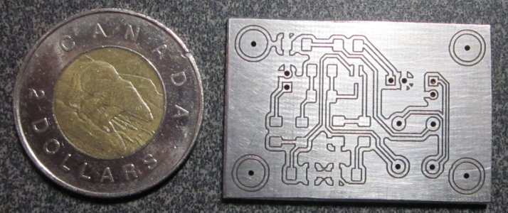
I’m a bit late to the party but thought I’d share my experiences regarding PCB making and workflow with my electronic projects. I make all my own PCB’s myself using the isolation routing method. I initially joined this group to learn as much as I could about CNC machining as my objective was to build up a system to make PCB’s and some smaller metal parts for RF projects. I built up a CNC controller from scratch based on an Arduino controller running GRBL firmware and I use a Sherline mill & isolation routing to machine my boards. I have made many boards using this technique, mostly double sided. I begin the process by entering my schematic design in the circuit simulator LTspice. I spend a lot of time here optimizing it and when I have it working well enough, I take the schematic into KiCad to do the board layout. I spend a lot of time at this phase too since I try to not only optimize circuit layout but also attempt to use as many of the parts that I have on hand. This usually involves building custom footprints. Typically, everything I do is a one-off. When I’m happy with the layout, KiCad outputs the Gerber and drill files. I take these into another app called FlatCam which produces the g-code. These are loaded into a PC running an application called bCNC. This is connected to the Arduino and the CNC XYZ controllers via an RS232 serial port. After origin settings for XYZ are zeroed, I turn on the mill and hit start.

As I also do 3D printing, I use Fusion for designing enclosures and many other items but not yet used it for PCB layout. I have never found KiCad lacking in any area. Almost everything I do involves SMD’s. I can make boards to support 0802 but most of the time I try to stick with 1206 size. One, this size is reasonably easy to work with and second, I have a good selection of SMD’s in that size. Equipment-wise I am also well set up for SMD work including a stereo microscope which makes them easy to work with and easy on the old eyes. Another technique I like is to make generic plug-in carrier PCB boards using Amazon parts – sockets, pins etc. Larger DIP IC’s are hard come by these days but surface mount IC’s are cheaper and readily available. Then I plug these carrier boards into a small motherboard and use wire-wrapping for interconnects. Changes are easy so this method lends itself well to prototyping.
SMD_FBA.JPG
 
Back
Top