From the info you provided, sounds to me the bearings are too tight. As things warm up, the bearings expand hard into their cups and thus friction increases dramatically requiring more power to turn the spindle. Also, they don’t seem to be lubricated sufficiently, thus accelerating the heat build-up.
Oil seals:
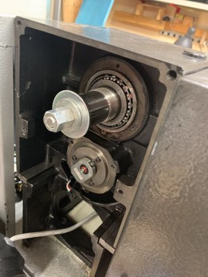
Your lathe uses a labyrinth seal. You can see the two oil collector grooves (red arrow) and the return passage (green arrows).
View attachment 19408
The oil seal ring just needs a thin layer of oil resistant RTV (the black goop you see ((blue arrow)) to seal the ring to the HS. This ring also retains the bearing cup (outer race).
Edit: on closer inspection, it looks like there is a paper seal stuck to the HS. The black goop is probably just seal retainer compound.
View attachment 19409
Did you remove the oil plug (yellow arrow)? It could be why the oil level will not go above the 3/9 position in the sight glass. The oil level in the HS will never be higher than the lowest point of the labyrinth seal as any excess will just run out between the seal and the spindle. So, in theory, you can not overfill the HS with oil.
Q 3
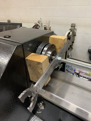
Yes, you can use the retaining nut to push the bearing cone (inner race) back onto the seat. A suitable tube could also be used to drive the cone back onto the spindle.
If you make a puller using ready rod, you could pull the spindle out the front.
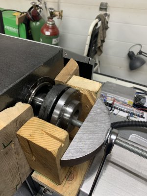
You could try and use a heat gun on the rear bearing to help with removal. I doubt the cone is anything more than a very light press fit onto the spindle; it needs to be able to move relatively freely as it is used to set the pre-load of the system.
What kind of retaining / pre-load system is used on the spindle? Just the nut? In that case it would set the pre-load for the spindle bearings. The manufacturer would specify a preload. They would probably specify it in terms of torque required to turn the spindle in its bearings (without anything connected to it).

")