Good to see you getting back to the project!
-
Scam Alert. Members are reminded to NOT send money to buy anything. Don't buy things remote and have it shipped - go get it yourself, pay in person, and take your equipment with you. Scammers have burned people on this forum. Urgency, secrecy, excuses, selling for friend, newish members, FUD, are RED FLAGS. A video conference call is not adequate assurance. Face to face interactions are required. Please report suspicions to the forum admins. Stay Safe - anyone can get scammed.
-
Several Regions have held meetups already, but others are being planned or are evaluating the interest. The Calgary Area Meetup is set for Saturday July 12th at 10am. The signup thread is here! Arbutus has also explored interest in a Fraser Valley meetup but it seems members either missed his thread or had other plans. Let him know if you are interested in a meetup later in the year by posting here! Slowpoke is trying to pull together an Ottawa area meetup later this summer. No date has been selected yet, so let him know if you are interested here! We are not aware of any other meetups being planned this year. If you are interested in doing something in your area, let everyone know and make it happen! Meetups are a great way to make new machining friends and get hands on help in your area. Don’t be shy, sign up and come, or plan your own meetup!
You are using an out of date browser. It may not display this or other websites correctly.
You should upgrade or use an alternative browser.
You should upgrade or use an alternative browser.
Hey forum.
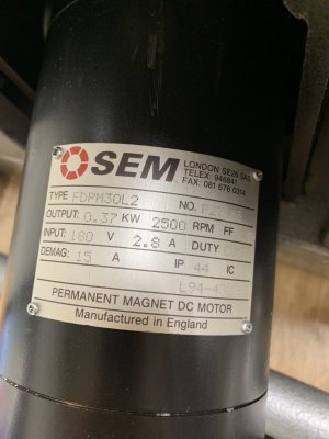
I keep blowing fuses trying to run the little guy at 3000 rpm. The motor says 2500 rpm on the plate. It’s a dc motor. The fuses are 8amp. There are two of them in the minarik brand motor drive. Any advice here?
I keep blowing fuses trying to run the little guy at 3000 rpm. The motor says 2500 rpm on the plate. It’s a dc motor. The fuses are 8amp. There are two of them in the minarik brand motor drive. Any advice here?
Attachments

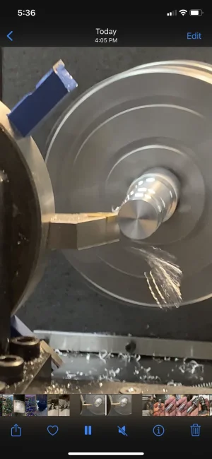
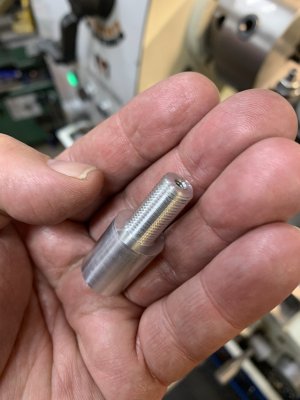
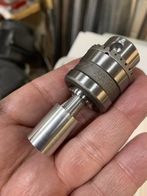
Made a real part on the cnc lathe today. I did the roughing in the lathe but the threading I simply did manually with a die. It’s a arbor for the small drill chucks I bought. One end is .625” diameter round and the other is 3/8-24 threaded. Spun the chuck onto the arbor and applied loctite. Here are a few pictures.
Attachments
-
 5C65B4E3-B5F4-4B53-B130-88D8F71E5FF7.webp80.2 KB · Views: 29
 -
 7C3D7356-E10B-4908-B416-5BC077E1B2A9.jpeg257.8 KB · Views: 30
 -
 89D9982C-AB9B-4086-BCF2-5CEBFC1820D5.jpeg336 KB · Views: 33
 -
 9EBB36BF-E9F1-4BA0-941A-EA731854EA00.jpeg305.9 KB · Views: 32
 -
 EF8F1EB6-30CB-4B01-AE5A-BC8FDA95F3B0.jpeg348.2 KB · Views: 33
 -
 D750FC84-E830-42FA-BB12-08AB12E84536.webp101.4 KB · Views: 123
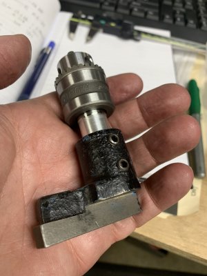
If you notice in picture 2 above there is also a threaded hole to take a screw down the throat of the chuck. The instructions said that should be a left hand thread and left hand bolt. I don’t have either so I just used a conventional #6-32 machine screw. I then used loctite on the threads. Will that hold?
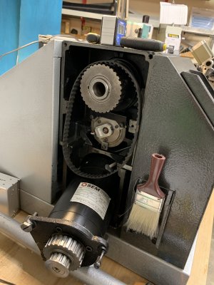
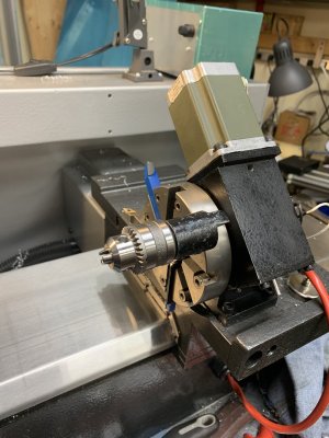
That is the rotary tool holder. Holds 8 tools. It’s motorized and spins each tool into position automatically. I still have to figure out the calibration for it. I can manually spin the tool into a close position and then use a straight edge to dial it in to centre.What is this thing with all the carbide tooling in it......?

That is the rotary tool holder. Holds 8 tools. It’s motorized and spins each tool into position automatically. I still have to figure out the calibration for it. I can manually spin the tool into a close position and then use a straight edge to dial it in to centre.
Amazing that such a "quick change" tool holder has enough rigidity to actually work! I would think the cranking gears take one heck of a beating! I'd there a locking lug of some kind?
I believe the mechanism is very similar to a rotary table. Worm gear?Amazing that such a "quick change" tool holder has enough rigidity to actually work! I would think the cranking gears take one heck of a beating! I'd there a locking lug of some kind?
I believe the mechanism is very similar to a rotary table. Worm gear?
Ya but rotary tables have a lock. Mine has two. To work with a motor drive like that, that thing can't have a lock. All the force will have to be reacted by the gear. I think it's a lot to ask of it.
There is another fix for that @Tom O. In the setup for the haas post checkmark G0 for rapids. below... But perhaps that is only available if you subscribe?Same as the Haas then I have to change the feed rate from 650 to 400 for the program to work using fusion 360.
Ya but rotary tables have a lock. Mine has two. To work with a motor drive like that, that thing can't have a lock. All the force will have to be reacted by the gear. I think it's a lot to ask of it.
Hmm. As a counter example it's reasonable to turn the handle on a RT while milling. It must be a pretty fine gear as it is 40 turns of the motor to move the next tool into position.
Videos....
Pardon the shaky camera. Tool changer.
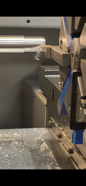
Speeds and feeds. It is aluminium. 900 RPM. diameter about 5/8". DOC 0.010" on the diameter. Feed is 0.001" per rev.
The part is the arbor to hold a drill chuck in the 90 degree tool holder you can see in the tool changer video at the top. It needs to be threaded 3/8-24 on the small diameter section. I also need a tapped hole in the end I think #8. Post #28 shows more pictures.
Pardon the shaky camera. Tool changer.
The part is the arbor to hold a drill chuck in the 90 degree tool holder you can see in the tool changer video at the top. It needs to be threaded 3/8-24 on the small diameter section. I also need a tapped hole in the end I think #8. Post #28 shows more pictures.
Last edited:
This is some good work John! Also I totally agree any machine moves outside the part should be G0 @Tom O. the main reason is while proving out the program you can keep the feed rate at 100% and turn the rapid way down. This helps on the first run through a part. Depending on how your machine is set up it may actually last longer if you use rapid. Most controllers have different breaking and resolution on a rapid move than a feed move. The Mazak I run actually has sliders to adjust accuracy, breaking acceleration and resolution.
Well folks I need some help. Kevin suggested shouting out to @RobinHood Rudy @johnnielsen @Dabbler the John's and anyone else who knows this stuff.
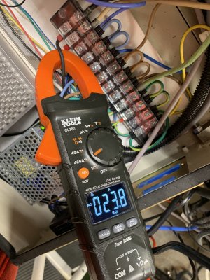
I was finding I can't spin the little lathe faster than 2100RPM now without blowing a breaker. While I was trying to diagnose this as an electrical problem I discovered that I don't think it is - I think it's a lubrication problem. Why do I think that? Well...I was running the lathe at a lower speed like 1800 rpm for a long time 20-30 minutes. Then suddenly I smelled something rubbery stinky, the lathe slowed way down and the current I was measuring went way up. I caught a max current on another attempt of 23A - that will trip the 15A breaker - picture 3! I hit emergency stop and noticed the headstock was quite warm AND the spindle was suddenly hard to turn. I took the belt off and the spindle was still hard to turn. Then I was looking at the oil sight glass. I thought it was ok (see below pic 5) but I grabbed some 32 oil and poured it in trying to get the level up. I then turned the spindle and amazing it spun like glass easier than it ever has. Then the next trouble started all the oil I put in started leaking out all over at both ends of the spindle. I couldn't get the sight glass fuller than just above the markers at 3 and 9 o'clock. Picture 5 below shows the sight glass. Is that too low? what is full? Is it at the top or the middle ok? That's my first question.
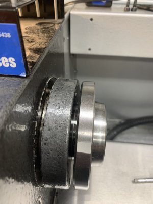
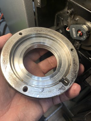
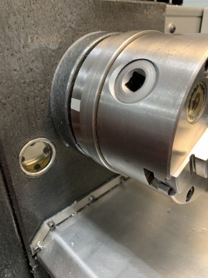
The second question is the leaking oil. Picture 2 shows the bearing (Timken 11162). Fitting over the bearing is the cover - aluminium - which has a close machined fit on the outer most lip to the flange outside edge. Picture 4 shows the cover. I expected to find a gasket but no. The cover and the flange have some hard black guck stuck on which might be gasket glue mostly removed? Would that be how the oil seal is made? Anyway both bearing covers leak. How would these covers be sealed? That's question 2.
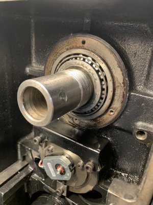
Question 3 everybody is the spindle body is mated (by friction?) to the bearing inner housing and I don't know how to take it apart. I tried gently tapping on it with a dead blow and it's in there pretty good. I wanted to take it out because there is no access to the second bearing cover as seen in picture 1. How should the spindle be removed from the bearing? I've never done anything like this so I didn't feel comfortable whacking it hard. Is taking it apart a bad idea? How do I reassemble it? There is a big nut that goes on to the spindle on the threaded section just sticking out past the bearing. Picture 2. Would tightening that up pull the spindle back into the bearing properly? How tight?
Thanks!
Thoughts?
I was finding I can't spin the little lathe faster than 2100RPM now without blowing a breaker. While I was trying to diagnose this as an electrical problem I discovered that I don't think it is - I think it's a lubrication problem. Why do I think that? Well...I was running the lathe at a lower speed like 1800 rpm for a long time 20-30 minutes. Then suddenly I smelled something rubbery stinky, the lathe slowed way down and the current I was measuring went way up. I caught a max current on another attempt of 23A - that will trip the 15A breaker - picture 3! I hit emergency stop and noticed the headstock was quite warm AND the spindle was suddenly hard to turn. I took the belt off and the spindle was still hard to turn. Then I was looking at the oil sight glass. I thought it was ok (see below pic 5) but I grabbed some 32 oil and poured it in trying to get the level up. I then turned the spindle and amazing it spun like glass easier than it ever has. Then the next trouble started all the oil I put in started leaking out all over at both ends of the spindle. I couldn't get the sight glass fuller than just above the markers at 3 and 9 o'clock. Picture 5 below shows the sight glass. Is that too low? what is full? Is it at the top or the middle ok? That's my first question.
The second question is the leaking oil. Picture 2 shows the bearing (Timken 11162). Fitting over the bearing is the cover - aluminium - which has a close machined fit on the outer most lip to the flange outside edge. Picture 4 shows the cover. I expected to find a gasket but no. The cover and the flange have some hard black guck stuck on which might be gasket glue mostly removed? Would that be how the oil seal is made? Anyway both bearing covers leak. How would these covers be sealed? That's question 2.
Question 3 everybody is the spindle body is mated (by friction?) to the bearing inner housing and I don't know how to take it apart. I tried gently tapping on it with a dead blow and it's in there pretty good. I wanted to take it out because there is no access to the second bearing cover as seen in picture 1. How should the spindle be removed from the bearing? I've never done anything like this so I didn't feel comfortable whacking it hard. Is taking it apart a bad idea? How do I reassemble it? There is a big nut that goes on to the spindle on the threaded section just sticking out past the bearing. Picture 2. Would tightening that up pull the spindle back into the bearing properly? How tight?
Thanks!
Thoughts?
Attachments
-
 554773FE-4B4C-4197-AC7A-B9073C06E2CA.jpeg323.2 KB · Views: 24
 -
 3BCDFE4D-164A-431F-9363-88A49463A692.jpeg481.9 KB · Views: 23
 -
 AE1BFE50-E51D-4523-B66D-643628266AAE.jpeg451.3 KB · Views: 30
 -
 B85567AB-32B6-4D0D-8445-BE6014D4FC6B.jpeg410.8 KB · Views: 26
 -
 A59522FB-64A1-4FED-B6A9-613DAA3A5C80.jpeg329.7 KB · Views: 27
Last edited: