• Spring 2024 meetup in Calgary - date Saturday, April 20/2024. discussion Please RSVP Here to confirm and get your invitation and the location details. RSVP NOW so organizers can plan to get sufficient food etc. It's Tomorrow Saturday! you can still RSVP until I stop checking my phone tomorrow More info and agenda
  • We are having email/registration problems again. Diagnosis is underway. New users sorry if you are having trouble getting registered. We are exploring different options to get registered. Contact the forum via another member or on facebook if you're stuck. Update -> we think it is fixed. Let us know if not.
  • Spring meet up in Ontario, April 6/2024. NEW LOCATION See Post #31 Discussion AND THE NEW LOCATION

Restoration/Repairs on a 10" LD Utilathe - Standard Modern

YYCHM

(Craig)
Premium Member
Yes,

AR Williams was the distributer used when the British company bought out Standard and modern and combined them. I have the same plate. My lathe is using a 1 HP motor - I think it is original to the machine and would have been an “option”. Reason I believe it is original is that I peeled the same design of motor off a similar circa 9” Utilathe.

Here is mine:

View attachment 10116

Brent, why does every lathe I see but mine have the compound canted over like that? Is that the magic thread cutting angle that I have never found to make a difference? Seems to me, it defeats the calibration of the compound dial?
 

Brent H

Ultra Member
@YYCHobbyMachinist - yes Craig , yes - that is the magic 29.5° degree angle ......oh man .... Ninjas!!! ——- ahahahahaah

But yes Craig, I typically leave my compound at 29.5 for threading. For most folks it would not be that important as you would be making stuff different all the time. My shop teach worked in the ship yards and that is the setting for the compound!!!!!
 

PeterT

Ultra Member
Premium Member
The compound is usually positioned (or left remaining) wherever it makes most sense. Pre-setting at threading angle is smart if that operation is forthcoming because after turning, the threading toolholder is popped on, cutter is therefore perpendicular & ready for 29.5-deg infeed. Or maybe the part has no threads but lots of 45-deg internal/external chamfers, then 45-deg is a good compound angle. Or if you need to bring the tailstock in for support, the compound may be interfering with TS so may have to be swivelled deeper to the left. Many compounds have a rectangular footprint as opposed to a round-ish footprint so it may lie more rigid swiveled to an angle where cutting forces act through more base material in that orientation. If you mount a toolpost grinder you can set the compound out to the right to nearly parallel with the lathe axis, that way a dial increment on the compound equates to a much smaller increment of equivalent in-feed. Some people like to cut like this too like creeping up on a critical dimension. Or, you can join the Kool Klub, yank your compound off altogether & install a solid toolpost LoL
 

Attachments

  • SNAG-7-16-2020 0000.jpg
    SNAG-7-16-2020 0000.jpg
    50.5 KB · Views: 0

PeterT

Ultra Member
Premium Member
No not mine Rudy. I've been collecting links & ideas & that pic was just pulled from my stash. I should have qualified that.

I've noticed different methods of fixing the toolpost by Rob.R, Stefan.G & others. Some keep it permanently square, locked with a dowel pin or angle plate on TP corner or something that looks like a mitee-bite looking cam clamp. I'm not sure if that has more to do with desire to accurately interchange tools or just removing any trace of assembly gap for max rigidity.

Personally I would still like the ability to detente the toolpost to in-between angles because certain turning ops just require the wedge/toolblock to be at some non 0-90 angle. I think the solid block vs. the sliding compound might provide majority of increased rigidity & vibration dampening so as long as the TP can be locked down sufficiently, so maybe best of both worlds? Its just a hunch right now. One thought (like the pic) was to have a dowel pin in either the base or TP and it matches a radial pattern of reamed holes in the other surface. So you would loosen the TP nut, lift TP slightly to clear extended dowel, rotate & drop into new index position & clamp down again. Or fancier maybe have half-sphere divots in the base & a sprung bearing ball in TP so it goes click,click every 15-deg or whatever but you could still position to some odd angle. Neither of these would lend themselves to the secondary locking mechanisms mentioned though.

But I have some design decisions to make so will do a CAD model. Most everyone has drilled new holes in their cross slide casting to give the widest bolt pattern footprint (within the limits of the dovetail underneath) so when the time comes I want to do it right the first time. I'd like a more stable base for toolpost grinding in particular. I know my compound assembly is a source for vibration even though the gib is locked. So in that mode the TP is removed leaving only the base block. It would be nice to make it adaptable to grinder mounting too. So far just pipe dreams!
 

Dabbler

ersatz engineer
I would still like the ability to detente the toolpost to in-between angles

Both Aloris and Dorian now make indexable QCTP versions. On my 15" my 4 way has 12 indexed postions. BTW I'm solidly in the 30 degree camp, not the 29.5 - sorry @Brent H

I had been dreaming and collecting materials for a solid toolpost for my 12" lathe. Now that it is slated for sale, that project is defunct. Curiously, my QCTP for the 15" is just a tad low (around 1/4"), so I might make an indexing plate for it to see how indexing a QCTP is a benefit or not....
 

Johnwa

Ultra Member
I’d say I’m in the 29 to 30 degree camp when threading. Just enough to scrub the back side of the thread. The rest of the time it’s all over the place.
I’ve considered an indexing plate for my toolpost mainly to bring it back to 90 degrees. But then I’d have to make sure my compound was at a consistent angle.
 

RobinHood

Ultra Member
Premium Member
I've been collecting links & ideas & that pic was just pulled from my stash. I should have qualified that.

No worries Peter. I knew you were thinking about a solid tool post - thought maybe you had a chance to make one.
 

RobinHood

Ultra Member
Premium Member
With HSS tooling I tend to have the compound at 30* for all SAE & Metric threading.

If I use carbide threading inserts, it is at 30* for ~12 TPI and coarser (to reduce the cutting pressure). Finer than 12, I just plunge in - so the compound is usually parallel to Z on the Colchester (no DRO). // to Z makes it easy to face to precise dimensions; the travel dial on the carriage only reads in 0.010”. Compound is in whatever the last position was on the SM1340 (it has a DRO).
 

Brent H

Ultra Member
Today was awesome and I needed to resurrect the old thread to add some information. Since the big rebuild I have been waiting on making a few more gears and just getting things dialled right in. When things are going well I can get the lathe to less than 0.0005” over a foot or more, and yes I can be picky - hahahahaha -

One thing that was bothering me was that when operating back from the headstock, near where you might start a cut on a longer shaft type thing I noticed that when I started to advance the saddle of the lathe it would slightly lift or deflect at the front. I thought this very odd - especially since I still was getting decent cut results - most of the time.

The second thing that bugged me was the play when advancing the apron. If you were threading the hand wheel would sometimes rock back and forth making little bumps.

Before heading to work I thought to just tear things apart and take some measurements- then the epiphany!!

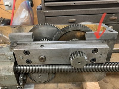
when rebuilding the lathe apron there is a plate (page 13 part number 3) “Gib Plate” but nothing more is referenced.
It is indicated by the red arrow:
3ED22FB4-326B-4259-976B-E8FE74DEFD78.jpeg
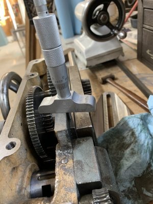
So with Spidey Senses tingling I did some measuring. Well- Ha! One side (back side) was 0.614” and the front was 0.624 - Interesting— so then I measured under the lathe from the machined surface of apron to the lathe bed and got an average of 0.610 with a bit of wear in spots but not bad. So “GIB PLATE” - light bulbs all coming on —— I loosened off the 4 Allen Head bolts and adjusted the GIB PLATE to be 0.612” front and back. Thinking 0.002” clear would be OK.
29C1BB87-C8C4-4294-BE2E-EF3286B6D93E.jpeg
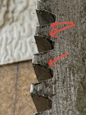
Then comes the second light bulb - way back when, @YYCHobbyMachinist bought a lathe in Ontario and @Chicken lights and I transported and shipped parts all over. One thing I kept back was the rack for the pinion that the hand wheel drives to advance the apron. Couldn’t be the same .... IT WAS !!! Ya baby - and it was pristine after an hour of scrubbing - compared to the one I had original on the lathe. Also the original had a bum retaining screw hole that would loosen from time to time - note the wear and raised edges:
3099D7E9-C3EE-460C-BC23-7C20651A2B3E.jpeg
So with all that changed out I adjusted the locking nuts on the Rear Saddle Gib and checked the fit of everything else - WOOO HOO! Less than 1/2 thou deflection if that and the apron was running super smooth! Still some play in the hand wheel but way way less - Excellent!!!

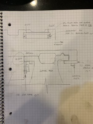
Here is a diagram that may help with clarity. The rear saddle Gib is mentioned in the manual but nothing about the front one.
5790E2CF-2E00-43FD-9608-007CCD4C403E.jpeg
Super cool - grabbed some other measurements for future projects - like a ball turner :). Since my other posting about black nuts was well received I figure a brass ball maker can’t go wrong :).
 

Dabbler

ersatz engineer
Nice illustration! Very well done! I have some PM to do on a couple of my aprons as soon as I get caught up on all the other things!

Great fix!
 

Brent H

Ultra Member
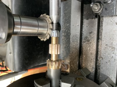
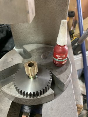
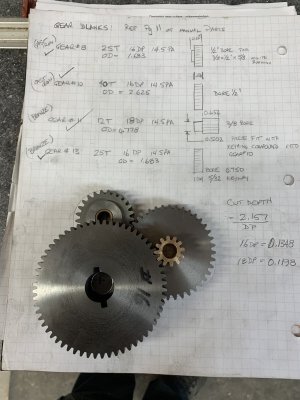
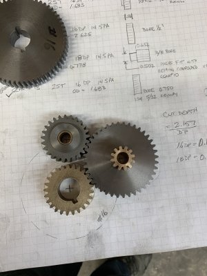
And the feed gear parts are finally done. Lathe is working fine with the present gears but I had the blanks and needed to get this completed.
61E028B9-5891-4DAA-9B7D-7B78E0F94E68.jpeg
E198408D-27E5-4D95-A8E0-1BCB6B2CC8C6.jpeg
6DE3A70D-A24F-492E-95BD-0CB3EDCAB5FC.jpeg
F4499059-8C83-4D9D-B242-1CF16ABF8D13.jpeg
The wee 12 tooth 18 DP bronze gear is loctited and pressed into the larger cast iron gear. The ID was then reamed to 0.375”. The grey gears are all impact resistant ductile cast iron and the gold gears are all bronze, I think they are 544 high stress bronze for greater wear resistance.
I have a couple more gears to finish for the outer drive but those are 20° pressure angle and, alas, I do not have those particular cutters - yet!!! BAHAHAHA.... cough cough -
 

Brent H

Ultra Member
Thanks guys :). I found that the “Chinese” cutters seem to have a few out of round issues - maybe a couple thou. To combat that I make sure the depth is set to the cutter tooth that just touches the work first. You will see a bit of the “chatter” type pattern in the wee bronze gear. The gears mesh well so things must be going ok - LOL.

I had the rotary table set up in the mill so finished off the gears I could as I need the mill for making a few other items - ahh the fun!!!
 

Salem747

Member
@Salem747
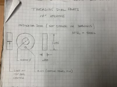
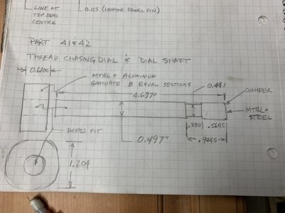
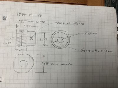
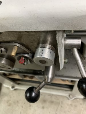
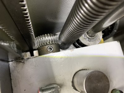
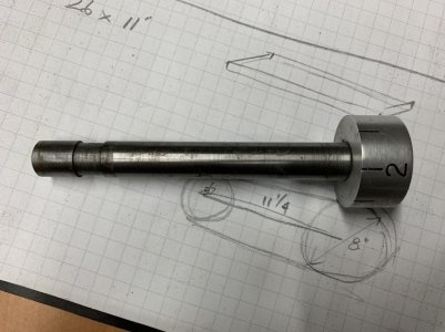
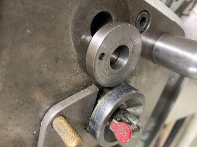
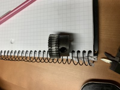
Here are some pics and drawings of the threading dial assembly:

View attachment 14640
View attachment 14641
View attachment 14642
View attachment 14643
View attachment 14644

View attachment 14645
View attachment 14646
View attachment 14647
@Salem747 : that is what I have for you at this time. Hopefully that can get you on track.
Oh snap! So that gear runs on the round shaft AND the spur gear! Wow. I wonder if lablonde can make this.

How do you index it? Hmm.
 

RobinHood

Ultra Member
Premium Member
Actually only the lead screw engages/drives that gear.

The picture above makes it seem as if it engaged both the carriage rack above and the lead screw below at the same time. It does not.
 

Salem747

Member
Actually only the lead screw engages/drives that gear.

The picture above makes it seem as if it engaged both the carriage rack above and the lead screw below at the same time. It does not.
Ok, I wonder why they shaped it that way, maybe to engage the round lead screw better?
 

Brent H

Ultra Member
@Salem747 : the gear (#39 in the manual) is a worm gear and rides on the lead screw. On the Utilathe the lead screw is 7/8” diameter and 8 threads per inch acme. The worm gear (I will have to check on measurements etc is a 24 DP 14.5 PA.

To index it properly, (do this at the tailstock end of the lathe as you can tighten the set screw on the gear). With the set screw loose, move the apron until you can engage the thread handle. With the thread handle engaged, rotate the thread dial to a number. Once on the number, tighten the set screw securely. That should set your indication.
 
Top