• Spring 2024 meetup in Calgary - date Saturday, April 20/2024. discussion Please RSVP Here to confirm and get your invitation and the location details. RSVP NOW so organizers can plan to get sufficient food etc. It's Tomorrow Saturday! you can still RSVP until I stop checking my phone tomorrow More info and agenda
  • We are having email/registration problems again. Diagnosis is underway. New users sorry if you are having trouble getting registered. We are exploring different options to get registered. Contact the forum via another member or on facebook if you're stuck. Update -> we think it is fixed. Let us know if not.
  • Spring meet up in Ontario, April 6/2024. NEW LOCATION See Post #31 Discussion AND THE NEW LOCATION

Radial engine build

PeterT

Ultra Member
Premium Member
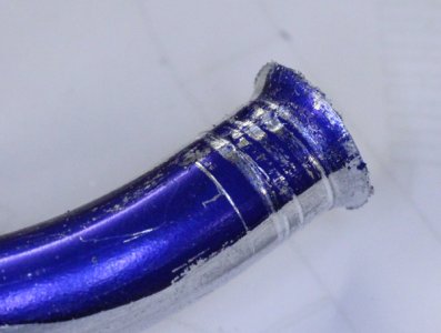
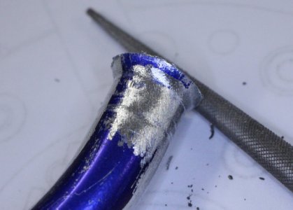
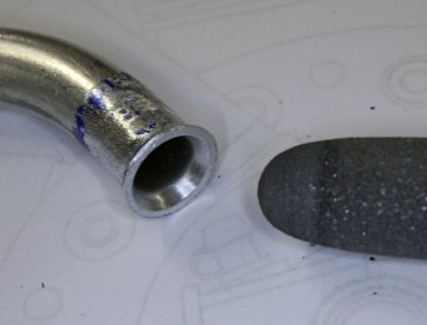
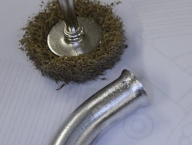
The flaring block ID is lightly threaded in order to grip the tube otherwise it slips back during flaring. The marring looks worse than it is. Needle file cleanup & the flange OD gets dressed to fit the port hole
 

Attachments

  • IMG_4068_edited-1.jpg
    IMG_4068_edited-1.jpg
    218.4 KB · Views: 6
  • IMG_4071_edited-1.jpg
    IMG_4071_edited-1.jpg
    197.1 KB · Views: 6
  • IMG_4072_edited-1.jpg
    IMG_4072_edited-1.jpg
    191.8 KB · Views: 5
  • IMG_4074_edited-1.jpg
    IMG_4074_edited-1.jpg
    203.9 KB · Views: 6
Last edited:

PeterT

Ultra Member
Premium Member
Some cutting & fit up to what will be permanent nozzles glued in the manifold. The tubing/nozzle joint will have a short length of 8mm black silicon tubing overlap & little wire ring clamps.
 

Attachments

  • IMG_4076_edited-1.jpg
    IMG_4076_edited-1.jpg
    350.7 KB · Views: 10
  • IMG_4082_edited-1.jpg
    IMG_4082_edited-1.jpg
    348.5 KB · Views: 11
  • IMG_4085_edited-1.jpg
    IMG_4085_edited-1.jpg
    335.9 KB · Views: 11
Last edited:

PeterT

Ultra Member
Premium Member
Before all this, after I made the new manifold & single tester pipe, I realized an error on my part. A series of mounting bolts is partially blanked by the nozzle/tube because of the new tubing entry angle orientation. Therefore no way to get a hex wrench in there to tighten the cap screw, even ball ended hex. Some last minute fudging the nozzle & thankfully I used a loose fit clearance holes for M3 bolts on the manifold. I can barely drop the cap screw in & tighten it. Note to future self - remember those little design details like IT HAS TO BE ASSEMBLEABLE!
 

Attachments

  • EDT-2021-08-22 6.24.27 PM.jpg
    EDT-2021-08-22 6.24.27 PM.jpg
    28.4 KB · Views: 6
Last edited:

RobinHood

Ultra Member
Premium Member
Nice progress.

The flaring block ID is lightly threaded in order to grip the tube otherwise it slips back during flaring.

Could one put a close fitting steel plug inside the pipe for clamping?

The inside of the tube would then be prevented from deforming and thus increase the effectiveness of the clamping block. No threads might be required and thus would leave the outside of the tube without marks. If the plug had a little treaded hole in it, one could screw in an extraction screw to help in pulling it out after the flare is complete.
 

PeterT

Ultra Member
Premium Member
That's an good idea, never occurred to me. I basically mimicked what I saw on commercial units although I drilled probably most of my threads off so it would have just enough bite to hold, but ideally keep mangling to minimum. Another fellow suggested Cerrobend might have a similar effect of filling the ID with something solid, but I was trying to avoid all that melting business and I wasn't quite sure ow I would spot a plug of it but still leaving room for the flaring cone. These tubing parts are fiddly buggers for sure.

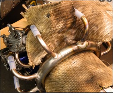
On a side note, radials typically have a ring exhaust collector as opposed to my rear facing open mini stacks which makes for more noise & oily goggles LoL. I've thought about how to form the big donut & making the connections. Some brave souls have done it. But for now the focus is just keep plodding forward towards making it run.
 

Attachments

  • SNAG-2021-08-22 10.33.24 PM.jpg
    SNAG-2021-08-22 10.33.24 PM.jpg
    89.5 KB · Views: 5
  • SNAG-2021-08-22 10.33.40 PM.jpg
    SNAG-2021-08-22 10.33.40 PM.jpg
    155.8 KB · Views: 5

RobinHood

Ultra Member
Premium Member
The ring exhaust on the full size engines must give some sort of performance advantage - be it to make it easier to route the exhaust stream overboard through one opening, controlling back pressure, or do some sort of exhaust tuning, etc. I am no engine expert and am only guessing. Now, on the full size engines the exhaust ring(s) is typically made from many individual sections either welded together or fitted inside each other and held by springs. It would be very difficult to make something like that in miniature. From the pictures you provided, it looks like some people have done it though…
 

Tom O

Ultra Member
What is the diameter of the ring? I would think that making two separate parts and silver soldered together would work.
 

PeterT

Ultra Member
Premium Member
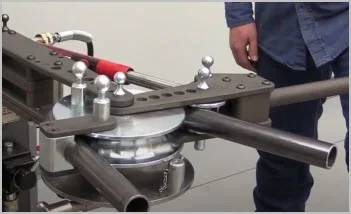
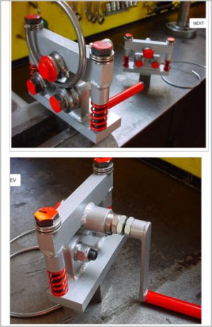
Tom, the plans didn't presume a collector ring but my eyeball guess would be maybe 7" diameter by maybe .75" section. I've been looking at different kinds of tubing rollers more out of morbid curiosity. I have a feeling this might fall in the geared crank handle style with multiple passes but I really don't know. I think a tool to roll things would be pretty useful. Some of the model locomotive builders pretty much need this kind of equipment but so far I have danced around the issue. In terms of material, more guessing. Lots of our conventional RC engines exhausts use aluminum but from what I can tell the collector rings I've seen seem to be thin wall steel for some reason. Probably TIG welded joints but that's just a guess.
 

Attachments

  • SNAG-2021-08-23 7.44.32 PM.jpg
    SNAG-2021-08-23 7.44.32 PM.jpg
    17.6 KB · Views: 8
  • SNAG-2021-08-23 7.45.07 PM.jpg
    SNAG-2021-08-23 7.45.07 PM.jpg
    54.7 KB · Views: 8

PeterT

Ultra Member
Premium Member
Sheesh, I am really falling behind on posting. Well, I made some progress on the pushrod tubes. I made the tappet bushings according to plans a long time ago. But once I had all the parts & engine assembled to this point, I could see some major issues.

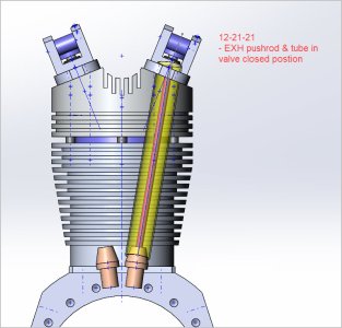
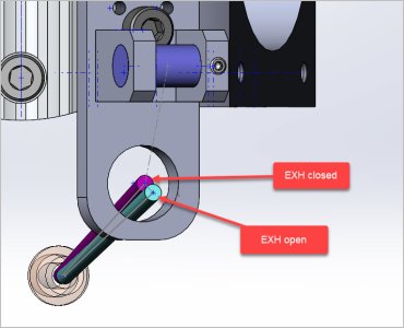
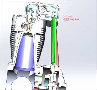
Number one, the pushrods enter the rocker boxes at different 3D angles. One angle component is related to how the rocker boxes sit on the head viewed from front relative to cylinder center line. The other angle component is because the intake & exhaust cam plates are fore & aft of each other, which is where the tappet/pushrod originate from. So intake & exhaust rocker box holes are different to each other. Something always seemed fishy with the plans in this regard. I could never make the parts fit in CAD, so so I drew it up from scratch. Things get more more interesting because the pushrod moves in a 3D motion. the bottom goes up & down an axis via the tappet, but the top moves in an arc via the rocker. So I found the min/max from cam throw & orientated the new hole center to the average point, then extruded a 3D hole into the rocker box plate. These aren't the actual drawings but hopefully show what I mean.
 

Attachments

  • EDT-2021-12-21 8.56.13 PM.jpg
    EDT-2021-12-21 8.56.13 PM.jpg
    136.4 KB · Views: 5
  • EDT-2021-12-21 8.57.22 PM.jpg
    EDT-2021-12-21 8.57.22 PM.jpg
    117.4 KB · Views: 5
  • EDT-2021-12-21 9.08.26 PM.jpg
    EDT-2021-12-21 9.08.26 PM.jpg
    70.3 KB · Views: 5
  • EDT-2022-01-21 9.42.03 PM.jpg
    EDT-2022-01-21 9.42.03 PM.jpg
    122.2 KB · Views: 5

PeterT

Ultra Member
Premium Member
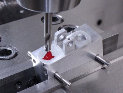
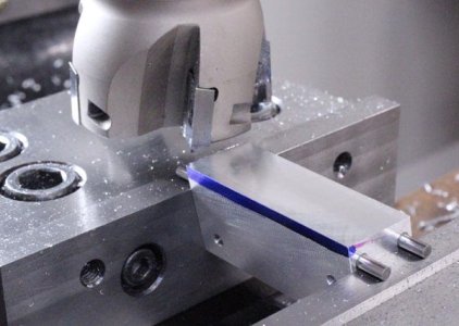
I made 2 separate fixtures to drill the 3D hole in the rocker box base. One fixture for intake, the other for exhaust. The angles are established by 3mm pins. One set establishes the perch datum which is shaved off the block. The other set positions the block to coincide with the fore-aft pushrod angle. 2 more pins to align the rocker. Indicate of 2 edges.... and finally drill the 7mm hole.
 

Attachments

  • IMG_4181_edited-1.jpg
    IMG_4181_edited-1.jpg
    62.6 KB · Views: 6
  • IMG_4180_edited-1.jpg
    IMG_4180_edited-1.jpg
    59 KB · Views: 6
  • IMG_4179_edited-1.jpg
    IMG_4179_edited-1.jpg
    55.1 KB · Views: 6
  • IMG_4168_edited-1.jpg
    IMG_4168_edited-1.jpg
    56.4 KB · Views: 6
  • IMG_4175_edited-1.jpg
    IMG_4175_edited-1.jpg
    56.7 KB · Views: 6

PeterT

Ultra Member
Premium Member
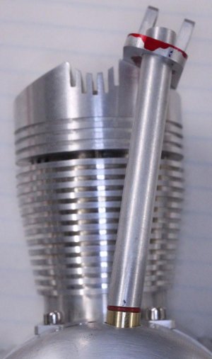
The 3D hole in the rocker box based fit perfect so that was established. Next issue was the pushrod tube. The plans called for bronze tappet bushings which a conical shape to kind of allow the tubing to rest on in a 3D-ish manner. I wasn't keen about metal on metal. To retain it in place he had a teeny M2 set screw drilled laterally in the rocker box base into a hole. None of this looked appealing. I posted a question here
https://canadianhobbymetalworkers.com/threads/pushrod-tubes.4388/

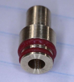
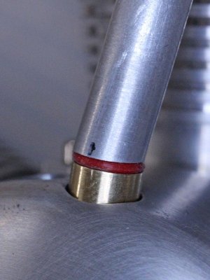
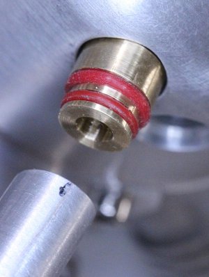
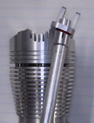
I made some silicone couplers molded off turned aluminum fixtures which turned out well considering how small they are, but I still wasn't wasn't thrilled by the chunky look & external clamps. So back to the drawing board. I made this prototype which has 2 O-rings. The upper O-ring seals against the pushrod tube ID & self centers the bushing. The lower O-ring is kind of a snub so the pushrod can sit on a bit of cushion, so no more metal to metal. It fits nice so now I have to replicate 10 in bronze.
 

Attachments

  • IMG_4387_edited-1.jpg
    IMG_4387_edited-1.jpg
    78.9 KB · Views: 6
  • IMG_4389_edited-1.jpg
    IMG_4389_edited-1.jpg
    77.2 KB · Views: 6
  • IMG_4390_edited-1.jpg
    IMG_4390_edited-1.jpg
    64 KB · Views: 5
  • IMG_4392_edited-1.jpg
    IMG_4392_edited-1.jpg
    57.2 KB · Views: 5
  • IMG_4395_edited-1.jpg
    IMG_4395_edited-1.jpg
    54.9 KB · Views: 6

PeterT

Ultra Member
Premium Member
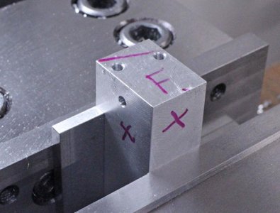
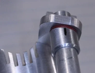
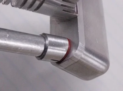
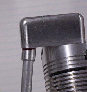
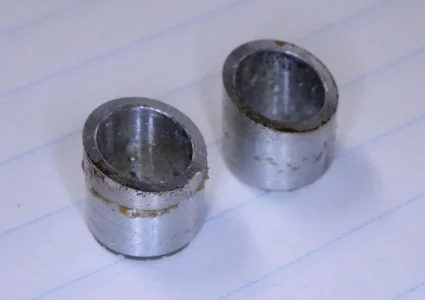
The last issue was how to retain the pushrod tube in the rocker box. I machined a collar which will eventually be bonded to the tube, but offset from the rocker box bottom surface just enough to accomodate another 1mm section silicone O-ring. The trick was to make that same 3D miter angle again on a fiddly little part. Here I cheated & just took care of the larger planar angle (12-15 deg) & hoped the O-ring squish would mask the fore-aft angle (1-6 deg).

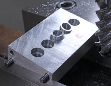
Another fixture plate where I can insert 5 exhaust couplers same time, plane off the angle, then repeat for intake. I tested 2 to see if the jig would work. I bonded with epoxy, milled the miter, then heated with torch to release. It held up during machining but cleanup took a bit longer. I used to have some hardware store 5-min epoxy that just softened, turned a toffee color & peeled off like wax. I ran out & used some of my good stuff & it put up more of a fight. It comes off with 3M pad eventually. Maybe I'll try CA glue but I've had mixed results with that too.
 

Attachments

  • IMG_4406_edited-1.jpg
    IMG_4406_edited-1.jpg
    68.4 KB · Views: 5
  • IMG_4414_edited-1.jpg
    IMG_4414_edited-1.jpg
    42.5 KB · Views: 5
  • IMG_4410_edited-1.jpg
    IMG_4410_edited-1.jpg
    44.5 KB · Views: 5
  • IMG_4407_edited-1.jpg
    IMG_4407_edited-1.jpg
    63 KB · Views: 5
  • IMG_4402_edited-1.jpg
    IMG_4402_edited-1.jpg
    38.1 KB · Views: 5
  • IMG_4399_edited-1.jpg
    IMG_4399_edited-1.jpg
    59.2 KB · Views: 5
  • IMG_4403_edited-1.jpg
    IMG_4403_edited-1.jpg
    48.6 KB · Views: 5

Gearhead88

Super User
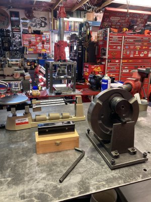
If the need arises to hone cylinders again , no matter the size , you can use my sunnen machine.
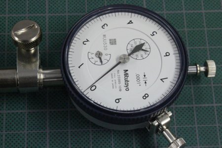
Tolerances of less than .0001" are possible , I have bore gauges to accomodate a variety of sizes .
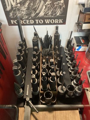
I have an abundance of mandrels , from spending too much time and money on ebay .

A small sample .....................
IMG_1479.JPG
 

PeterT

Ultra Member
Premium Member
If the need arises to hone cylinders again , no matter the size , you can use my sunnen machine.
Tolerances of less than .0001" are possible , I have bore gauges to accomodate a variety of sizes .
I have an abundance of mandrels , from spending too much time and money on ebay .

A small sample .....................

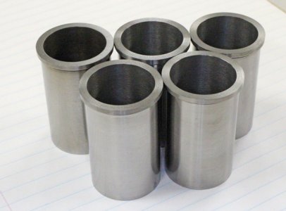
OooohhhYaaa. What a nice offer. We are definitely going to have to talk. Lapping these liners was not the most fun job in the world. Times two because I underestimated the amount of shrink once landed in the cylinders. What made it more challenging was creeping up & hitting a target tenth on all 5 cylinder bores (plus one spare). Because on this engine I'm using commercial rings. The better way is to make the liner bores 'all the same' & then make the rings on that measured basis. If the bores are a thou over or under doesn't matter as long as they are the same & within tolerance. I didn't feel confident enough to make my own rings at the time. Actually, more specifically, I didn't have wherewithal to heat treat them. So if this runs WHEN this engine runs, the next project will likely have more cylinders.
 

Gearhead88

Super User
OooohhhYaaa. What a nice offer. We are definitely going to have to talk. Lapping these liners was not the most fun job in the world. Times two because I underestimated the amount of shrink once landed in the cylinders. What made it more challenging was creeping up & hitting a target tenth on all 5 cylinder bores (plus one spare). Because on this engine I'm using commercial rings. The better way is to make the liner bores 'all the same' & then make the rings on that measured basis. If the bores are a thou over or under doesn't matter as long as they are the same & within tolerance. I didn't feel confident enough to make my own rings at the time. Actually, more specifically, I didn't have wherewithal to heat treat them. So if this runs WHEN this engine runs, the next project will likely have more cylinders.
A Sunnen hone will save a bunch of time . What I do is , my piston size is zero on my bore gauge , as I am honing I sneak up on that and once I’m on the plus side of zero that is my clearance , I can then put that measurement wherever I want it , very accurately . The trick is to keep the hole straight and round , not difficult when using the right abrasives and being mindful of cutting pressure and closely monitoring size / material removed as you go . You gotta use a bore gauge that measures to .0001”.
 

Gearhead88

Super User
I’m balancing a crankshaft today , I got bushings for the small end of the rods on Friday , oversized rod rollers & new cages too , so I could proceed , Once I had the bushings pressed in and sized . Everything gets weighed to a tenth of a gram , some calculations , then you build a bob weight to fasten to the crank pin hole on the flywheel . image.jpg
 
Top