• Spring 2024 meetup in Calgary - date Saturday, April 20/2024. discussion Please RSVP Here to confirm and get your invitation and the location details. RSVP NOW so organizers can plan to get sufficient food etc. One week to go! More info and agenda
  • We are having email/registration problems again. Diagnosis is underway. New users sorry if you are having trouble getting registered. We are exploring different options to get registered. Contact the forum via another member or on facebook if you're stuck. Update -> we think it is fixed. Let us know if not.
  • Spring meet up in Ontario, April 6/2024. NEW LOCATION See Post #31 Discussion AND THE NEW LOCATION

Radial engine build

PeterT

Ultra Member
Premium Member
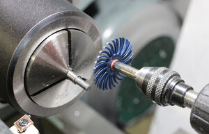
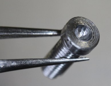
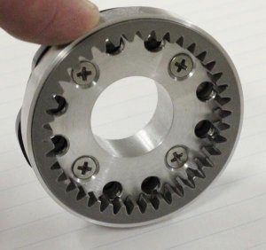
Give the threads a very slight sandover with 600 grit wet/dry paper bonded to a flat stick. I make my own by the dozen using 3M spray adhesive. This cleans up the tops of the crests which can have raised burrs from threading. Then with the chuck still spinning I use this rotary polishing spider which does a great job of cleaning the threads. I've gotten into this habit because it doesn't take much time & helps condition the threads. I found when I was single point threading fine threads, half the issue was +/- false measurements.

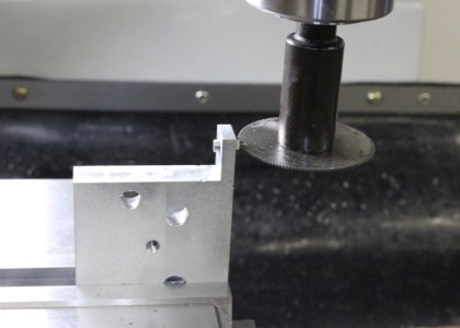
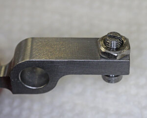
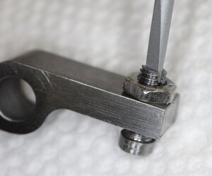
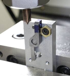
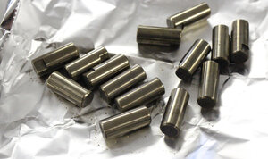
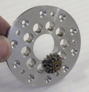
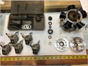
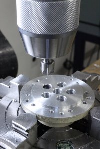
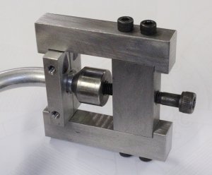
Leftover threaded jig so the head length can be be made batch mode.
 

Attachments

  • IMG_3708_edited-1.jpg
    IMG_3708_edited-1.jpg
    202.7 KB · Views: 8
  • IMG_3707_edited-1.jpg
    IMG_3707_edited-1.jpg
    202.5 KB · Views: 8
  • IMG_3709_edited-1.jpg
    IMG_3709_edited-1.jpg
    175.3 KB · Views: 7

PeterT

Ultra Member
Premium Member
Into a jig made from scrap aluminum. The part is threaded into a hole, then a nut to keep it put, then slit 0.025" x 0.050" deep. Then the 2mm ball end mill for pushrod end. Shows how it sits on rocker arm & jeweler screwdriver to make adjustment. Basically done aside from hardening them.
 

Attachments

  • IMG_3710_edited-1.jpg
    IMG_3710_edited-1.jpg
    173.4 KB · Views: 5
  • IMG_3711_edited-1.jpg
    IMG_3711_edited-1.jpg
    160 KB · Views: 5
  • IMG_3713_edited-1.jpg
    IMG_3713_edited-1.jpg
    184.8 KB · Views: 5
  • IMG_3715_edited-1.jpg
    IMG_3715_edited-1.jpg
    181.1 KB · Views: 5
  • IMG_3717_edited-1.jpg
    IMG_3717_edited-1.jpg
    158.9 KB · Views: 5
  • IMG_3719_edited-1.jpg
    IMG_3719_edited-1.jpg
    189.3 KB · Views: 5
  • IMG_3721_edited-1.jpg
    IMG_3721_edited-1.jpg
    168.2 KB · Views: 5

PeterT

Ultra Member
Premium Member
Some overdue items arrived in the mailbox. Aliexpress radius mills, so was able to finish the roundover profile on the rocker arms. 8-32 Mitee Bite claps so made for a convenient way to lock the arm position against a stop pin, flip the part & radius the other side.

I decided to lock the rocker axle from spinning so milled a flat & tapped a teeny M2 hole in the perch. the axles are hardened now.

The rocker perch get these rings Loctite in counterbore so they self align to the valve hole.

Fiddly bits, fiddly bits, endless fiddly bits....
 

Attachments

  • IMG_3739_edited-1.jpg
    IMG_3739_edited-1.jpg
    247.4 KB · Views: 7
  • IMG_3729_edited-1.jpg
    IMG_3729_edited-1.jpg
    147 KB · Views: 7
  • IMG_3741_edited-1.jpg
    IMG_3741_edited-1.jpg
    182.2 KB · Views: 5
  • IMG_3727_edited-1.jpg
    IMG_3727_edited-1.jpg
    156.4 KB · Views: 5
  • IMG_3726_edited-1.jpg
    IMG_3726_edited-1.jpg
    144.3 KB · Views: 5
  • IMG_3724_edited-1.jpg
    IMG_3724_edited-1.jpg
    175.5 KB · Views: 5
  • IMG_3732_edited-1.jpg
    IMG_3732_edited-1.jpg
    152.3 KB · Views: 4
  • IMG_3734_edited-1.jpg
    IMG_3734_edited-1.jpg
    160.5 KB · Views: 4

PeterT

Ultra Member
Premium Member
Thanks Johnwa, yes I've seen that vid. What impressed me is he is building a FS engine on hobby size lathe & mill. Never underestimate the power of a hobbyist amateur on a mission! LOL
Seems like VW engine parts are somewhat suited for aeronautical powerplants, at least among the homebuilt crowd. I've see other cylinder layout configurations.
 

PeterT

Ultra Member
Premium Member
Well I've been deliberating over the lubrication issue long enough, it was time to bite the bullet. The original design calls for the nose case to be partially filled with oil so that the cams & planetary gears get splashed. That part seemed pretty straightforward initially. But as time progressed some nagging thoughts I had started to become more clear. The nose case chamber is isolated from the crankcase with O-rings on the front gear plate which were kind of a PITA to make but they seal. Issue-1 is I think oil is going to get by the submerged tappets on the bottom side as they are working away. Issue-2 there is a crankshaft bearing in the nose case which is specified as sealed but I think oil is going to make its way backwards into the crankcase through the seals eventually. In methanol glow engines we always remove the internal shields because the methanol acts as a solvent on the grease over time. The premix oil is completely satisfactory to lubricate parts. The brief German instructions make reference to 'sealant & silicon' which makes me suspicious.

After some research I concluded this engine (well and his 9-cylinder) is the only one I've seen with an oil bath chamber like this. There are engines with scavenging oil pumps (to late for me). And there are engines including several commercial radials with apertures or windows that allow the raw intake charge mist to flow around & coat all internal parts. I was a bit concerned of the distance though, mist reaching forward ina tortuous path to coat the cam plates. But every RC engine I have ever dismantled is liberally coated with oil everywhere, all the nooks & crannies. Sometimes too much, often you find puddles in low areas. Many engines have a blow-by nipple to drain buildup fuel/oil residue.

So... I decided to modify my existing parts
- nose case will have a screw in fitting to squirt a bit of heavier weight oil over the cams before a run just for insurance
- front plate will have openings to allow forward mist flow
- ring gear cup will have holes to match the cam plate holes (which I did before hardening in case this day would come)
 

Attachments

  • 2019-11-19_23-45-43.jpg
    2019-11-19_23-45-43.jpg
    83.6 KB · Views: 7
  • IMG_7233_edited-1.jpg
    IMG_7233_edited-1.jpg
    186.8 KB · Views: 6
  • SNAG-11-24-2019 0002.jpg
    SNAG-11-24-2019 0002.jpg
    73.4 KB · Views: 7
  • SNAG-11-24-2019 0004.jpg
    SNAG-11-24-2019 0004.jpg
    97.2 KB · Views: 7
Last edited:

PeterT

Ultra Member
Premium Member
Putting these new features on the parts required stepping back & making jig plates so alignment could be established again. It would have been easier when the parts were made, but oh well.
Drill jig for ring gear cup which the cam plates are bolted too.
 

Attachments

  • IMG_4021.jpg
    IMG_4021.jpg
    390.6 KB · Views: 5
  • IMG_4023_edited-1.jpg
    IMG_4023_edited-1.jpg
    58 KB · Views: 5
  • IMG_4027_edited-1.jpg
    IMG_4027_edited-1.jpg
    56.3 KB · Views: 5
  • IMG_4029_edited-1.jpg
    IMG_4029_edited-1.jpg
    55.9 KB · Views: 5
Last edited:

PeterT

Ultra Member
Premium Member
Jig for modifying the front plate. Its a bit swiss cheesed with the new holes but its 2024 alloy & well supported so hopefully strong enough. I managed to get the 2 lower holes slightly intersecting the gear cluster so hoping it gets directly misted. Fingers crossed. I'll just have to be careful during break-in runs to open the nose case early & often to see how wet things are.
 

Attachments

  • IMG_4039_edited-1.jpg
    IMG_4039_edited-1.jpg
    59.4 KB · Views: 4
  • IMG_4038_edited-1.jpg
    IMG_4038_edited-1.jpg
    59.7 KB · Views: 4
  • IMG_4034_edited-1.jpg
    IMG_4034_edited-1.jpg
    59.1 KB · Views: 5
  • IMG_4031_edited-1.jpg
    IMG_4031_edited-1.jpg
    41.2 KB · Views: 7
  • IMG_4032_edited-1.jpg
    IMG_4032_edited-1.jpg
    62.1 KB · Views: 5
  • IMG_4030_edited-1.jpg
    IMG_4030_edited-1.jpg
    66.6 KB · Views: 6
  • IMG_4042_edited-1.jpg
    IMG_4042_edited-1.jpg
    65.8 KB · Views: 4
  • IMG_4043_edited-1.jpg
    IMG_4043_edited-1.jpg
    59.5 KB · Views: 4
  • IMG_4044_edited-1.jpg
    IMG_4044_edited-1.jpg
    55.9 KB · Views: 4
Last edited:

PeterT

Ultra Member
Premium Member
I found an RC post where a guy acquired a commercial radial made by O.S. & began refurbishing. Unfortunately it was in sad shape. The original owner just let it sit for a couple years, never inspected or applied after run / storage oil coating to parts. Between the methanol fuel & acids in the oil, corrosion can set in quick & get real ugly. But the pictures told me wherever there was rust there was fuel mist & it was alll over the cams, gears & bearings. AFAIK nobody has ever seized an engine in these areas. Seems primitive but I guess it works.
 

Attachments

  • SNAG-11-24-2019 0005.jpg
    SNAG-11-24-2019 0005.jpg
    57.4 KB · Views: 7
  • SNAG-2021-06-22 000.jpg
    SNAG-2021-06-22 000.jpg
    99.2 KB · Views: 7
Last edited:

PeterT

Ultra Member
Premium Member
The next thing on my 'less than happy' list is induction manifold assembly. The original design had the tubes going into counterbores with recessed O-rings to seal the tube. I wasn't keen on machining those but mostly the end result seemed sketchy on multiple fronts. How to get the candy cane intake tube in the hole landed in O-ring then shimmy the other end into the head with a threaded coupler over the trumpet end.... Ack! I could see those O-rings leaking & leaning out the mixture or worse. So I made extended manifold pipe-etts & figured I could mask the connections with a hose coupler. I was not thrilled by the geometry & miters but just put aesthetics aside for now.

Then (3 years after the fact) I started to think about the RC carb I bought & for which the manifold was machined to match. The plans mentioned an engine no longer produced. I thought it was a 0.40 CI engine, but turns out it was actually smaller. The issue is after a lot of searching & digging I'm pretty certain the 8mm venturi throat is too big for this engine, it should be more like 5.5-6.0mm. I'm not after max power necessarily but too big a throat & it doesn't draw fuel properly for idle & transition. Turns out RC engines are becoming more & more scarce these days as the hobby shrinks & people are going electric. I found some carbs online closer to correct size to test but the body diameters are different. So that was the final nail in the coffin. I decided to redesign the manifold & clean up all these issues simultaneously.
 

Attachments

  • IMG_3787_edited-1.jpg
    IMG_3787_edited-1.jpg
    176.6 KB · Views: 12
  • IMG_3985_edited-1.jpg
    IMG_3985_edited-1.jpg
    64.5 KB · Views: 12
  • IMG_3986_edited-1.jpg
    IMG_3986_edited-1.jpg
    53.8 KB · Views: 12
  • IMG_3987_edited-1.jpg
    IMG_3987_edited-1.jpg
    54.9 KB · Views: 9
Last edited:

PeterT

Ultra Member
Premium Member
The CAD exercise highlighted why my tubes were never going to match no-how. It would have to be a funky 3D shape to come off the head on one axis & end up in the manifold at another axis. The plans led me down the garden path. Its hard enough to bend tubing in 1 plane to a target angle, never mind this 3D challenge. I know some guys fill them with bizmuth or whatever but they still need to be shaped consistently.

So my plan is start with 'simple' tubes made from my fixed radius bender with straight segments on either side. Quite similar to what I have actually, but now the manifold ports will be properly realigned to suite. I also made provisions for a standardized carb adapter plate so I can just bolt on any carb with whatever body diameter & leave the manifold alone. I also altered the engine mount lugs which was another thing that bugged me. Slowly...moving....forward.....
 

Attachments

  • SNAG-2021-07-01 009.jpg
    SNAG-2021-07-01 009.jpg
    73.1 KB · Views: 5
  • SNAG-2021-07-04 12.48.04 AM.jpg
    SNAG-2021-07-04 12.48.04 AM.jpg
    133.9 KB · Views: 5
  • SNAG-2021-07-31 11.36.13 PM.jpg
    SNAG-2021-07-31 11.36.13 PM.jpg
    120.7 KB · Views: 6
  • SNAG-2021-07-31 11.36.51 PM.jpg
    SNAG-2021-07-31 11.36.51 PM.jpg
    112.8 KB · Views: 5
  • IMG_4014_edited-1.jpg
    IMG_4014_edited-1.jpg
    68.4 KB · Views: 5
  • IMG_4019.jpg
    IMG_4019.jpg
    454 KB · Views: 4

kevin.decelles

Jack of all trades -- Master of none
Premium Member
I always feel like a caveman after reading your posts. Thank you.

Fantastic stuff! Motivates me to keep learning. Keep it coming


Sent from my iPhone using Tapatalk
 

Proxule

Ultra Member
I am clearly late to the party but when I searched the forum I stumbled on the castings thread and steam engine stuff, This is a whole new world. Very impressive stuff peter, I must admit my reasoning behind my machinery is for this stuff ( steam engines / hit and miss / hot bulb etc etc ) as well. I will keenly keep an eye on this thread and read through it all and digest it ASAP.

Thanks for sharing and keeping this thread alive.
 

PeterT

Ultra Member
Premium Member
I don't think I showed making the intake pipes so here are some pics. As mentioned, I wasn't happy with the stock design manifold & how the pipes made those miters, but part of that was I was limited to my hand bender which had a defined radius. So bottom line was either make a custom bending tool in order to bend a specific radius (lots of work) or accept the bend radius of my tool & redesign the manifold & piping system around it (slightly less work).

Most of this stuff is specific to fitting the engine, so after some fudging experimentation it was basically repeat the ritual. The tubing is 5/16" OD aluminum Versatube from AS&S. Unfortunately they send the material coiled in a 6" box which is a PITA to straighten. I was too lazy & impatient to make the roller straightener tool but I will eventually. The pipe section is only about 4.5" long so I lightly pre-rolled it between to pieces of hard MDF pizza dough style until I had a straight segment to begin with.
 

Attachments

  • IMG_4089_edited-1.jpg
    IMG_4089_edited-1.jpg
    208.7 KB · Views: 4
  • IMG_4092_edited-1.jpg
    IMG_4092_edited-1.jpg
    195.4 KB · Views: 4
  • IMG_4093_edited-1.jpg
    IMG_4093_edited-1.jpg
    200.6 KB · Views: 4

PeterT

Ultra Member
Premium Member
Shows my trumpet flaring die. The plywood on the end is so I could cut the excess & face it exactly square. Then it has correct stickout for the flare. Slight chamfer helps
 

Attachments

  • IMG_4051_edited-1.jpg
    IMG_4051_edited-1.jpg
    208.2 KB · Views: 3
  • IMG_4053_edited-1.jpg
    IMG_4053_edited-1.jpg
    188.7 KB · Views: 3
  • IMG_4054_edited-1.jpg
    IMG_4054_edited-1.jpg
    164.2 KB · Views: 3
  • IMG_4056_edited-1.jpg
    IMG_4056_edited-1.jpg
    222 KB · Views: 3
  • IMG_4058_edited-1.jpg
    IMG_4058_edited-1.jpg
    242.8 KB · Views: 3
  • IMG_4059_edited-1.jpg
    IMG_4059_edited-1.jpg
    262.9 KB · Views: 3

PeterT

Ultra Member
Premium Member
My home brew flaring tool. That face gets dressed slightly too.
 

Attachments

  • IMG_4061_edited-1.jpg
    IMG_4061_edited-1.jpg
    213.2 KB · Views: 4
  • IMG_4063_edited-1.jpg
    IMG_4063_edited-1.jpg
    235.5 KB · Views: 4
  • IMG_4065_edited-1.jpg
    IMG_4065_edited-1.jpg
    228.2 KB · Views: 4
  • IMG_4066_edited-1.jpg
    IMG_4066_edited-1.jpg
    240.9 KB · Views: 4
  • IMG_4067_edited-1.jpg
    IMG_4067_edited-1.jpg
    234.7 KB · Views: 4
Top