NUMOBAMS 8x16 (NU-210G) Lathe Review

StevSmar

(Steven)
Premium Member
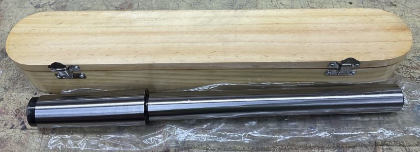
Only real disappointment was that the wood box was not very good and went straight in the trash.
My wooden box was as shown in the photographs. It was shipped a separate, identical cardboard box. Which I suspect was because the wooden box would have been destroyed by the weight of the test bar during shipping.
0D1533A8-6D06-4169-9B6E-A36FEC66E130.jpeg
I was happy with the purchase, which then gave me the confidence to purchase a knurling tool from the vendor.
 

Susquatch

Ultra Member
Administrator
Moderator
Premium Member
My wooden box was as shown in the photographs. It was shipped a separate, identical cardboard box. Which I suspect was because the wooden box would have been destroyed by the weight of the test bar during shipping.
View attachment 23839
I was happy with the purchase, which then gave me the confidence to purchase a knurling tool from the vendor.

Hey @StevSmar, Who is the vendor and what is the knurling tool you bought?
 

StevSmar

(Steven)
Premium Member
I want to get an offshore test bar to compare with my standard methods...
Based on my one try at using a test bar, I currently think test bars get you into the ballpark and after that turning two collars is really the true test.

I had about 0.002” runout on the end of my 15” test bar and unfortunately I don’t have enough tools to tell whether the runout was due to the lathes spindle bore or the test bar.

I’m still undecided if it was worth getting one.
Someone smarter than me is likely to add their two bits, but for most of us, .002" at 15" from the headstock sounds pretty good on a hobby lathe to me..... Now if it was Darren's 10ee or Rauce's Hendey, I might think otherwise......
 

Rauce

Ultra Member
Someone smarter than me is likely to add their two bits, but for most of us, .002" at 15" from the headstock sounds pretty good on a hobby lathe to me..... Now if it was Darren's 10ee or Rauce's Hendey, I might think otherwise......
I clocked .0006” on my test bar 12” out. Which would be some combination of error in the bar and magnified runout in the MT5 taper in the headstock.

Keep in mind that for the purpose of checking the carriage against the test bar the amount that the test bar would be off is half the TIR (assuming consistent OD). By turning the spindle and averaging readings as Mcgyver has detailed you can eliminate the runout from the equation.

I don’t think checking the bar takes much by way of equipment. A mic will check the OD along the length. You can check for bow by measuring runout between centres on your lathe or across a pair of v blocks.
 

Susquatch

Ultra Member
Administrator
Moderator
Premium Member
I appologize to everyone. I should have finished my experiments on this subject ages ago.

A factor that has not been mentioned is the effect of gravity on the test bar. It is easy to do a quick calculation but it will not be correct enough to use for this purpose because the material bending strength varies. I believe a measurement is better.

Bending due to gravity is the reason I decided to use a piece of pipe. Pipe has much higher resistance to bending from its own weight than bar steel could ever have.

Length magnifies the measurement but also adds more gravity error due to bending. I intend to measure this to determine the optimum length and pipe specifications.

Without having actually done this yet, I'll wager a bet that at 8" the gravity effect is negligible and at 12" it becomes important. I think that pipe might allow one to go to 16" or even 24.

More importantly, by actually measuring the bending, one can take it into account mathematically.

Again, without actually having done it, I expect that measuring it is as simple as hanging a weight at the halfway point that is equal to the unsupported weight of the bar and measuring the static deflection.
As this may look like an issue its not as it will have the same effect if the bar is measured from the bottom (or top) and the effect will remain constant. Now if the defection changes.....there is a misalignment.
 

Susquatch

Ultra Member
Administrator
Moderator
Premium Member
As this may look like an issue its not as it will have the same effect if the bar is measured from the bottom (or top) and the effect will remain constant. Now if the defection changes.....there is a misalignment.

I don't think that's true.

For the sake of simplifying the discussion, let's suppose we are talking about vertical misalignment only with no side to side misalignment.

A measurement at the head is is the reference. If you then measure at the far end of the bar, any bending of the bar due to gravity will look like vertical misalignment (pointing down) even if none is actually there. I believe that is why most alignment bars are relatively short.
In that case you are in real trouble as your bed of the lathe for it would have even more sag in the middle as it is supported at the ends on pivots.

Seriously in terms of deflection, the alignment bar does deflect a small amount, which you can calculate before hand (structural steel handbook has all the formulas, brings back memories in steel building design). Now if the deflection is say 0.000001 per ft (calculated) you consider that as zero. If its less then you head is pointed up, if its more then down.

I would see more influence in errors in a tool in cutting as it applies considerably more forces than gravity in substantially more directions at same time.

I would also add unless you stat looking into temperature if you are getting into this level of precision you are wasting your time as it will effect you readings even more given cast, steel, and a list of other materials used in the lathe.

I see this as chasing rainbows in terms of reading too much into measurements to achieve accuracy. Don't over complicate things.
 

Susquatch

Ultra Member
Administrator
Moderator
Premium Member
In that case you are in real trouble as your bed of the lathe for it would have even more sag in the middle as it is supported at the ends on pivots.

Seriously in terms of deflection, the alignment bar does deflect a small amount, which you can calculate before hand (structural steel handbook has all the formulas, brings back memories in steel building design). Now if the deflection is say 0.000001 per ft (calculated) you consider that as zero. If its less then you head is pointed up, if its more then down.

I would see more influence in errors in a tool in cutting as it applies considerably more forces than gravity in substantially more directions at same time.

I would also add unless you stat looking into temperature if you are getting into this level of precision you are wasting your time as it will effect you readings even more given cast, steel, and a list of other materials used in the lathe.

I see this as chasing rainbows in terms of reading too much into measurements to achieve accuracy. Don't over complicate things.

I think one of us has flawed math.

But, besides the fact that I am prejudiced to prefer my own version, I'll also pick my version simply because you indicated the deflection is linearly proportional to length. ("Now if the deflection is say 0.000001 per ft (calculated)... ").

That is clearly not correct. The deflection is not linear with length.

My math calculates 3 tenths for a 12" bar of average strength (30,000ksi) and a diameter of 1.125" (chosen only for convenience to have a cross sectional area of 1 sq-in to simplify the calc).

For a 16" bar, the calculated deflection is about 1 thou. And for a 2ft bar it is 5 thou.

This compares favorably with the results determined using on-line calculators and other references for Lathe alignment bar deflection I looked at in the past. It is also specifically mentioned in numerous places as the reason for using a shorter bar.

This is also the reason that I am exploring the use of a pipe. A pipe (cylinder) has a much better second moment of area to weight ratio.

Lastly, your comments about how these numbers affect the use of the lathe and alignment of the head suggest maybe we are not on the same page on that subject either.

As others have pointed out, some lathe designs cannot be easily adjusted. Some can be adjusted with great difficulty, and some are just difficult. I've never heard of one that was easy. In my own case, it is just difficult. Mine is done using the six base feet which are used to change the bed twist as well as the head alignment.

For those who have non-adjustable heads, the only purpose of testing the alignment is to know what it is. For the rest of us, it's good to be able to get it as close as practical.

For obvious reasons, a long bar makes it easier to detect small angular differences. But the deflection caused by its own weight works against that.

Your comments about simply taking the deflection into account reflect my own thoughts. If it's negligeable (as it is for short lengths) then as you say, I don't need to worry about it. But since I'd prefer to use a longer bar to magnify the measurement, it probably won't be negligeable. In that case, it must be accounted for.

I don't think accounting for it is as simple as a calculation. Yes, the calculation can get you close, but a measurement can get you bang on. Once you know what it is, I agree with your comments that you can simply adjust your alignment measurements accordingly. Hence my reason for wanting to know what it is...... LOL!

I plan to do some actual measurements in the near future. I'll certainly find out then whose numbers are correct. Those measured numbers will have a profound effect on the final design of my proposed test bar with replaceable collars.

In the meantime, I have ordered an MT5 test bar to use for comparison purposes. And then we will see what we will see about all of this.

I also agree with your comments about the affect of tool pressure. But it's also unknown. So I want to measure it and develop a procedure to accomodate it.

As long as it is stabilized and constant, I don't think temperature is that important for this application. My shop is temperature stable and I always warm my equipment up before any precision work. But that is just an opinion. I have no information or data to suggest otherwise. Nonetheless I am fairly confident that it is much less important than quantifying the weight deflection issue.
 
The number I used was just for example, not an actual number.

As to how beam deflect as forces are applied depends greatly on how the they are mounted, in some case become very complex in mathematical solution. As you suggested the use of 6 point leveling system does give you control but it also adds variables that are very undersireable. (BTW my new lathe has this too ;)).

As to temperature it does have a bigger effect than you suspect, so much so it was part of an engineering lesson (lab).

Regardless of the deflection if you know what it is, it allows you to confirm whether or not the head is aligned or not. If the calculated value at 2' is 5 thou, measure close and measure at the end, if it 5 thou, you good, if not start tweaking.
 

Susquatch

Ultra Member
Administrator
Moderator
Premium Member
As to temperature it does have a bigger effect than you suspect, so much so it was part of an engineering lesson (lab).

Oh, I think you totally underestimate what I know about such things..... And of course, I probably overestimate it. LOL!

Frankly, I think you and I are just worried about opposite ends of extremes. In my opinion, temp effect is an easy calculation that is insignificant for what we are talking about here. I see this as chasing rainbows in terms of reading too much into it. Don't over complicate things. LOL! (Sorry, Devil made me say that - just using the same words you used earlier for the humour effect!)

Anyway, in this case the radial expansion is well below my ability to measure it and I don't believe that longitudinal expansion matters in this application. In case you are wondering, the average coefficient of thermal expansion for steel is just 0.00000645in/in/deg F.

Rather than chasing MY tail, which is not something I'd be wanting to do if I were you, I'd suggest you wait until I complete my assessment of this whole subject in designing my new collared system. I'll have actual measurements and comparison testing of other methods at that time and I will make all of it available for peer review on my thread for that. I'd like to believe that I will be totally open to any and all criticism or suggestions for improvements that anyone cares to provide at that time.
 

Susquatch

Ultra Member
Administrator
Moderator
Premium Member
@Susquatch since we've spoke by phone, I think we speak and see the same things so a good educational banter helps others.

I think both of us have a little OCD.

And here we go again at opposite sides of two extremes. I believe you have totally underestimated me again. I do NOT have a little OCD.

I have at least two orders of magnitude higher OCD than a little.

And that is actually significantly reduced in intensity ever since I passed 65 right in tune with my vision, my hearing, my coordination, and my memory.
I've learned to understate things, helps keeping people off guard. ;)

BTW me too.
 

StevSmar

(Steven)
Premium Member
…For a 16" bar, the calculated deflection is about 1 thou. And for a 2ft bar it is 5 thou...
Does it matter whether the test bar sags? Isn’t the primary reason for using a test bar for adjusting twist? The measurement on the vertical face of the test bar is not going to see much of a change in radius from sag.
(Edit: I did a sketch in Fusion 360 to see what 0.001” sag will do for a reading of the vertical face. It's smaller than what Fusion can display...)
(I first did the sketch with a 0.01 sag to make sure I had the sketch constraints correct, then I changed the 0.01 dimension to 0.001)

Test bar sag for Canadian Hobby Metalworkers.jpg
…This is also the reason that I am exploring the use of a pipe. A pipe (cylinder) has a much better second moment of area to weight ratio…
What about a carbon fibre pipe test bar? That would look very nice too!
 
Last edited:
Top