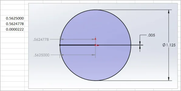
That was the point of my sketch, except I didn’t present it as clearly as you have.
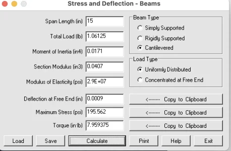
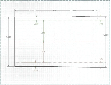
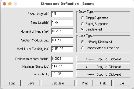
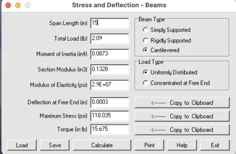
My sketch suggested for a 1” test bar that has deflected 0.001”, the change in DTI reading was something like 0.000001” (too small for Fusion360 to give an actual dimension)
I had only addressed
@PeterT's concern about dynamic bending. But your note suggests that perhaps you guys are also talking about something else. Or perhaps I misunderstood the dynamic bending discussion too.
Sometimes the English language sucks. On reflection, I am not at all sure that I understand what either of you are talking about when you say that a 1 thou deflection results in a 0.000001 dti reading. I suspect you are thinking that the measurement of the test bar is taken on its side where a typical tool cut is made. And the very tiny measurement you refer to is the change in the dti reading that results from a slightly higher position on the radius of the shaft caused by its droop. (that was a mouthful) If so, that isn't the idea at all.
Setting dynamic deflections aside for now, it might help if I explain a little more about what I believe we are trying to do here.
Ideally, we want the axis of our spindle to be parallel to the axis of the ways. However, this isn't always the case. The axis of the spindle could be pointing down or it could be pointing up (let's call both of those nod) and it could also be pointing forward or rear ward (let's call that wag).
A rigid and solidly mounted cutting tool held in a tool holder on the cross-slide will always slide along the ways on a path that is parallel to the axis of the ways. This is a fundamental aspect of the way that a lathe works.
If the lathe spindle axis wags inward toward the operator. The lathe will end up cutting a taper that is smaller at the far end of a bar than it is at the headstock. If it is pointing away from the operator, the far end will be fatter. Because the cutting tool is located at the vertical center of the spindles axis of rotation, the angle of the resulting taper will be proportional to the wag angle of the spindle itself. This angle can be calculated by measuring the taper. The taper measurement is taken with a Micrometer not a DTI.
On the other hand, a cutting tool that travels the length of a test bar that points up or down does not cut as big a taper. That's because the cutting tool moves up or down the radial surface of the test bar as it traverses left or right. The result is a MUCH smaller taper. Perhaps this is the 0.000001 measurement you guys referred to. And of course, you are correct - this effect is relatively insignificant. Not only that, but it's insignificance IS IMPORTANT. Because the taper caused by any up or down nod is insignificant, the test bar will be more or less cylindrical. And because it is cylindrical, the nod can be measured. Not by measuring this insignificant taper, but rather by directly running a DTI (NOT a Micrometer) from left to right along the TOP of the test bar. A spindle that points up will result in a higher measurement at the end of the test bar, and one that points down will result in a lower measurement.
Because nod is measured on the top of the bar, any deflection of the bar due to its own weight can interfere with a precise measurement. However, if the deflection is known, it can simply be subtracted from the nod measurement.
Of course, there are many other ways to do this measurement and other equipment that can be used. But fundamentally, nod is measured on the top of the bar and wag is measured on the side.
Nod and wag are two separate measurements. However, any taper caused by wag must be subtracted from or added to the nod measurement.
Fans of the MT test bar will no doubt be quick to point out that the test bar does not require measuring tapers. Instead both nod and wag are measured directly with DTIs - at the top for Nod, and on the side for Wag.
At the risk of re-opening an old debate, I believe the mt5 test bar method is much easier to do but that any concentrity error in the bar or MT5 socket, or any dirt in the MT5 connection will result in errors that need to identified and cancelled out.
On the other hand, cutting a test bar requires a very sharp cutting tool, and a complicated taper measurement.
Both will work just fine as long as you know and understand their limitations.
I hope that helps.