I have a couple ideas - #1 don't use adaptive instead use straight slot milling. #2 just run the program again and see if a spring pass removes that remaining 0.005 to 0.010". Thoughts ?
-
Scam Alert. Members are reminded to NOT send money to buy anything. Don't buy things remote and have it shipped - go get it yourself, pay in person, and take your equipment with you. Scammers have burned people on this forum. Urgency, secrecy, excuses, selling for friend, newish members, FUD, are RED FLAGS. A video conference call is not adequate assurance. Face to face interactions are required. Please report suspicions to the forum admins. Stay Safe - anyone can get scammed.
-
Several Regions have held meetups already, but others are being planned or are evaluating the interest. The Calgary Area Meetup is set for Saturday July 12th at 10am. The signup thread is here! Arbutus has also explored interest in a Fraser Valley meetup but it seems members either missed his thread or had other plans. Let him know if you are interested in a meetup later in the year by posting here! Slowpoke is trying to pull together an Ottawa area meetup later this summer. No date has been selected yet, so let him know if you are interested here! We are not aware of any other meetups being planned this year. If you are interested in doing something in your area, let everyone know and make it happen! Meetups are a great way to make new machining friends and get hands on help in your area. Don’t be shy, sign up and come, or plan your own meetup!
You are using an out of date browser. It may not display this or other websites correctly.
You should upgrade or use an alternative browser.
You should upgrade or use an alternative browser.
New vise jaw product
- Thread starter Janger
- Start date
- I agree with @RobinHood that deflection appears to be the issue and a larger EM would help or eliminate the problem (pardon my total lack of milling experience, but I don't know the meaning of "spring passes"). Keeping the EM as short as possible will also help.
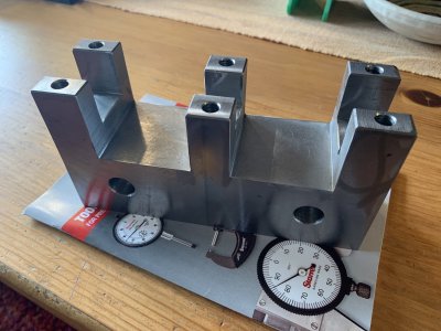
- At the start of cutting down into the notch, the material below the EM is keeping the relatively short columns from defecting and any deflection is coming from the EM. But during the last few passes, the increasing height of the columns could cause the columns to deflect. Then both the EM and the column height are contributing to the total deflection (particularly if the columns were thinner or taller). I think this problem would be worse if you rough-cut the notch ID to say 0.980" and then did a full-height finish cut of 0.010" off of both columns.
- It appears that you are clamping the bottom of the part (pic in post 109) and you are milling in a N-S direction (y-axis). Consider rotating the part 90 degrees, lower it as low as possible in the vise and then mill E-W (x-axis) so that the vise jaws can (help) keep the columns from deflecting. Alternately, If you want to mill N-S (because of program, view, where you put your beer, or whatever) then rotate both the vise and the part 90 degrees so that you can lower the part in the vise.
Craig


I am studying machine design and would really like to take a look at the CAD files for this as it seems to hold some complex design strategies.Turns out Norgen the manufacturer has detailed CAD models on their web site. Hiding inside are some very sophisticated parts. The mechanism to hold all the vise fingers tight has some sliding angled bits. It has to hold all the fingers tight and also hold them tight against the side of the vise sled. below you can see this mechanism with parts hidden on the right, the same view on the left showing the vise sled and vise fingers, and below some of the insides of the sliding angle part. I don't understand it. inside there is a cone that has threads and somehow is connected to mvoe the sliding angled part?
$6K does not seem so unreasonable to me now - this must have taken a lot of design and testing work to get it working well. I wonder what it cost them to develop?
View attachment 23035
View attachment 23036
I looked at the link but for life of can't find where I can download them from.
Do you think you could send me a link or even the files themselves?
Thanks
Timely post @Janger . I watched a video the other night on a similar flexible design vise but it used a resovoir filled with small ball bearings. There is an air gap and as you close the vise the balls are shifted/squeezed to make room. Eventually all the space is full and the jaws cannot move.
Problem is I don’t remember where I watched it. Still looking. Cool concept
Problem is I don’t remember where I watched it. Still looking. Cool concept
Tom O
Ultra Member
I saw the same one too found it!Timely post @Janger . I watched a video the other night on a similar flexible design vise but it used a resovoir filled with small ball bearings. There is an air gap and as you close the vise the balls are shifted/squeezed to make room. Eventually all the space is full and the jaws cannot move.
Problem is I don’t remember where I watched it. Still looking. Cool concept
Last edited:
Fantastic!
The video is more of a how to restore the vise and a lot less on how it actually works (humph). The ball bearing part makes sense - as you tighten the vise the space behind the jaws shrinks until it is all gone and the jaws tighten against the balls. The bar though passing under the jaw teeth is less clear what it is doing. I grabbed a couple screen captures - it appears to have a rectangular section cut out of the bar and the bar rotates I think to hit a flat on the teeth. I'm not certain though what it is doing. Is that a small lip on the bar? When you tighten the handle what is happening exactly? On the norgren I think the side handle clamps the fingers together. Not sure what is happening here.


The ball bearing flexible jaw vise is both ingenious and relatively simple. Or should I say simply amazing.
Sawzall can shaker - I cut off the bristle portion of a SS brush and attached that to an old sawsall blade. It works great for cleaning aluminum before welding.
Sawzall can shaker - I cut off the bristle portion of a SS brush and attached that to an old sawsall blade. It works great for cleaning aluminum before welding.
@Janger - In your post 109 above you had an issue with your vise speed wrench - here is my Version 2.0 of a speed wrench. The handle portion is a bit heavy so that when it is closed it is balanced. Version 1.0 didn’t work as well because it could conflict with the Y axis feed wheel. This one is more compact when closed. It spins quick & easily, has no conflicts, and when open it’s longer than a standard vise wrench.
Version 3.0 is coming soon (maybe). It will be made from aluminum and have an improved detent (out of the way the back) to hold it in both the open and closed positions.


Version 3.0 is coming soon (maybe). It will be made from aluminum and have an improved detent (out of the way the back) to hold it in both the open and closed positions.
Cool handle. I like the detent.@Janger - In your post 109 above you had an issue with your vise speed wrench - here is my Version 2.0 of a speed wrench. The handle portion is a bit heavy so that when it is closed it is balanced. Version 1.0 didn’t work as well because it could conflict with the Y axis feed wheel. This one is more compact when closed. It spins quick & easily, has no conflicts, and when open it’s longer than a standard vise wrench.
Version 3.0 is coming soon (maybe). It will be made from aluminum and have an improved detent (out of the way the back) to hold it in both the open and closed positions.
RobinHood
Ultra Member
The bar though passing under the jaw teeth is less clear what it is doing. I grabbed a couple screen captures - it appears to have a rectangular section cut out of the bar and the bar rotates I think to hit a flat on the teeth. I'm not certain though what it is doing. Is that a small lip on the bar? When you tighten the handle what is happening exactly?
In a nutshell, it resets the jaws from their “adapted“ position to the fully extended, ”even” position. The cam underneath the jaws engages in the notch in the bottom of each jaw and the rotation of the cam, with the reset lever on the side, moves the jaws out.
The flat, milled out section on the cam is needed so that the jaws can slide back over the cam when the vice is tightened and the jaws “adapt“.
Edit: The sketch shows the max travel of a jaw. The steel balls may stop it before it reaches its rear limit, depending on the shape of the object being clamped.
Sorry for the ‘napkin CAD’… don’t have any computer CAD software.
Great post Rudy I think you've explained it well.In a nutshell, it resets the jaws from their “adapted“ position to the fully extended, ”even” position. The cam underneath the jaws engages in the notch in the bottom of each jaw and the rotation of the cam, with the reset lever on the side, moves the jaws out.
Sorry for the ‘napkin CAD’… don’t have any computer CAD software