• Spring 2024 meetup in Calgary - tentative date Saturday, April 20/2024. Other regions are also discussing meet ups. If you want one in your area get going on organizing it! discussion
  • We are having email/registration problems again. Diagnosis is underway. New users sorry if you are having trouble getting registered. We are exploring different options to get registered. Contact the forum via another member or on facebook if you're stuck. Update -> we think it is fixed. Let us know if not.
  • Spring meet up in Ontario, April 6/2024. NEW LOCATION See Post #31 Discussion NEW LOCATION

New to me Bridgeport Mill

Susquatch

Ultra Member
Administrator
Moderator
Premium Member
For next time, I've got a stash of various size woodruff keys. Not all sizes but quite a few. They came from an auction lot a couple of years ago.

Will do! And much appreciated.

Maybe if I decide the keep the BP instead of the Hartford, I'll replace the home made key with a proper one. If I do that, I'll be in touch.

Thanks!

Anybody know if there are any special metal requirements for woodruff keys? Hardness, metal type, etc? In other words, is my home made key doomed to fail because it's made from plain cold rolled 1/4" plate?
 

RobinHood

Ultra Member
Premium Member
Anybody know if there are any special metal requirements for woodruff keys? Hardness, metal type, etc? In other words, is my home made key doomed to fail because it's made from plain cold rolled 1/4" plate?

Like in so many things - it depends on the situation. I think a well fitting key made out of A36 is superior to a sloppy alloy steel (SAE 1035) one.

Here is a little blurb on woodruff keys:
https://www.huyett.com/blog/woodruff-keys
 

Susquatch

Ultra Member
Administrator
Moderator
Premium Member
Like in so many things - it depends on the situation. I think a well fitting key made out of A36 is superior to a sloppy alloy steel (SAE 1035) one.

Here is a little blurb on woodruff keys:
https://www.huyett.com/blog/woodruff-keys

Great stuff.

One quibble with the article. It indicates that they are normally regular grade steel but designed to shear. But in my experience, shear pins/bolts/keys are normally hardened. Grade 5 is common. That prejudices them to fail in shear as intended (hence the name) instead of bending deformation which often ruins the mating parts.

I repair a lot of farm equipment. The three main causes of damage that I see are improper fastener torque, failure to follow the greasing schedule, and using regular grade bolts as shear bolts when grade 5 Bolts are specified.
 
Last edited:

Susquatch

Ultra Member
Administrator
Moderator
Premium Member
After breaking an end mill, and getting member advice on the cause, I decided to adjust the Gibbs and backlash.

I got the X backlash down to 75 thou at the ends and 85 in the middle. Thats 25 thou less than before. But that's where the screw bottomed out. So I assume that's all there is without replacing or modifying the nut.

Oddly, I got the Y Axis down to the same 75 & 85 thou and then also ran out of adjustment screw travel. I assume both lead screw assemblies are just equally well worn.

I also tightened the X Y and Z Gibbs as much as I could without fear of breaking the Gibb screws. It's still not tight because it's still easy to move the table on both axis. Locking any of the Gibbs makes it very difficult to move them so I assume I have simply run out of adjustment on the Gibb screws too. I don't plan to do any more Gibb or leade screw tightening until I decide which mill to keep. If I keep the Bridgeport, I'll probably replace the leade screw assemblies and gibbs

I also discovered that the y axis lock was out of sync with the table and while I thought it was working, in reality it wasn't locking anything. It now locks the Y Axis solid as a rock.
 

Susquatch

Ultra Member
Administrator
Moderator
Premium Member
That hole goes all the way through. It is not cylindrical. The diameter on the upper surface (facing us) is larger than the diameter where it comes through the plate at the back. Only reason I can think of this would be for is to center the lever pin in the hole without play.

The little cut-outs you see on the edges are only 1/2 the plate thickness.

Sorry for not being clear enough. It’s always easier to “see things” when the part is right in front of you…

@Brent H, @Dabbler, @RobinHood @YYCHM, and anyone else who contributed to the resolution of this issue.

I made my first mill repair part this morning using the Bridgeport the part is for. The plate is machined out of a small piece of 1/2" plate left over from torching out the motor adapter plate for my Hartford. It's too bad I didn't take a before picture. It looked a lot like this......

20210826_163043.jpg

First I ground one side flat and then worked my way around adding referenced sides one at a time and then milling it down to a flat plate 0.185 thick, 0.700 wide, and 0.600 long to fit the slot. Then I used some black grease to mark the plunger path, and then milled a slot to match the path.

Here is the result. It works great!

20210826_153603.jpg

Another problem resolved.

Still waiting on the belt for the Hartford so I can get that mill working too and then make a final decision.
 
Last edited:

Susquatch

Ultra Member
Administrator
Moderator
Premium Member
I noticed that the sector mesh on the knee crank is a bit mashed up. Probably from loosely engaging it before using it.

I also noticed that most of the photos I see show the crank reversed as though in storage.

I'm thinking about drilling and tapping the end of the shaft for a 10-24 screw and installing a washer stack or a custom keeper made on my lathe to hold the crank on firmly so it cannot wear any further.

Is that a bad idea for some reason that I can't yet appreciate?
 

Brent H

Ultra Member
@Susquatch, depending on your inseam and the handle position, you may find you speak an octave or two higher if you leave the crank out while you are moving around the mill.

I leave mine out when I am in operation but store it when I am fussing about.
 

Susquatch

Ultra Member
Administrator
Moderator
Premium Member
@Susquatch, depending on your inseam and the handle position, you may find you speak an octave or two higher if you leave the crank out while you are moving around the mill.

I leave mine out when I am in operation but store it when I am fussing about.

Wow, for serious! I've always wanted to sing tenor....

I'm quite tall but I suppose walking into it is a potential issue. Actually, I'd be more worried about my wife. She might leave me for a machine.....

OK, so I need to rethink the screw and washer block a LOT more. Needs to be a quick release system of some kind.......
 

RobinHood

Ultra Member
Premium Member
As Bent says: you want it removable after use. It may be worn on the castellations and have engagement issues with the Z-axis screw, but boy howdy, will it ever engage your lower body parts. I left it hanging out once thinking since I am careful around machines, it’ll be fine. Not.
 

Susquatch

Ultra Member
Administrator
Moderator
Premium Member
Everyone knows “ Daddy sings bass Momma sings Tenor “ View attachment 16832

That's too funny! I sing that all the time. But I always add "me and little sister sing along". The grandkids LOVE it. Thx for that.

Thinking one of those mechanisms that you push button to release would work.
 

Susquatch

Ultra Member
Administrator
Moderator
Premium Member
As Bent says: you want it removable after use. It may be worn on the castellations and have engagement issues with the Z-axis screw, but boy howdy, will it ever engage your lower body parts. I left it hanging out once thinking since I am careful around machines, it’ll be fine. Not.

OK, I'm convinced. Noodling a quick release now.

"Castellations" eh..... Way better word than my "sector mesh". Thanks for that.
 

RobinHood

Ultra Member
Premium Member
Just what I always called them - only because they look like a castellated nut. There probably is a proper milling machine term for it.
 

Susquatch

Ultra Member
Administrator
Moderator
Premium Member
Just discovered another Bridgeport Problem that needs to be fixed asap.

I was doing just regular maintenance and discovered that one of the big 1/2 Bolts holding the Turret to the base is stripped. It would not take the specified torque. Usually the bolt strips before the nut so I hoped that was the case this time too. No such luck.

I guess the previous owner over torqued it. Why do so many people hate torque wrenches?

Obviously, it needs to be fixed. I'll probably thread it oversize or shave down the old nut and weld on a new one.

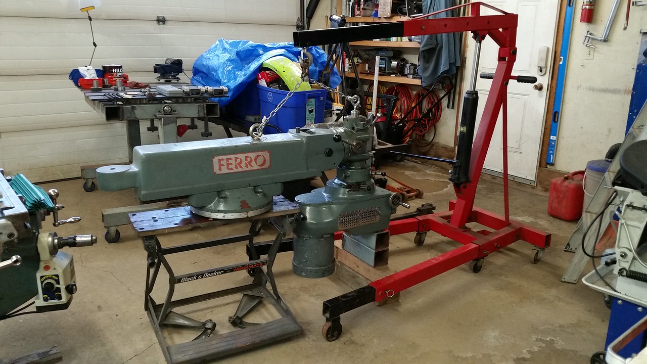
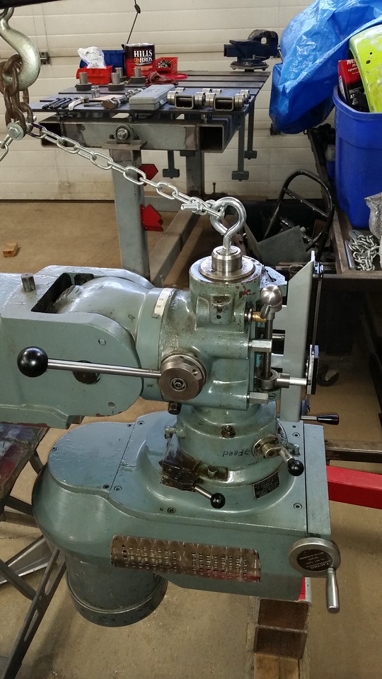
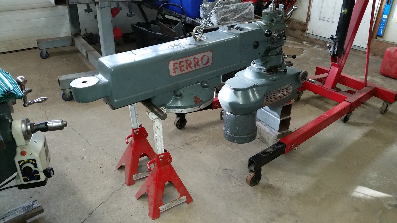
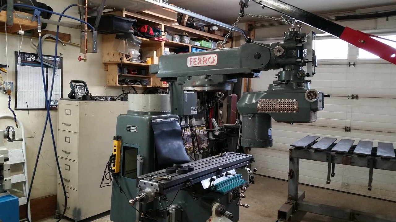
But first I need to take the ram off. I'm thinking of strapping up the motor so it doesn't try to flip, and then using a chain fall on an eye bolt in the top of the ram. That eye bolt is strong enough to hold the entire mill so it should be easily strong enough to to hold the ram and motor. I'm really only worried about the ram flipping.

I suppose I could remove the whole head before removing the ram, but it seems a bit overkill.

Any advice on this one?
 

Dabbler

ersatz engineer
In all the very old BP manuals, it shows a big red X about lifting the entire machine by that eye bolt. The ram is about 1/2 - 5/8 " thick at the eye bolt, so it is a iffy lift at best. I usually lift using a pair of staps on both sides of the ram when lifting a whole machine. - and even that has it's pucker factor.

lifting the an with the motor on can be done, but here's a much easier, safer, and quicher way, especially when considering reassembly:

If you know how, take the head assembly off the ram. (more on that if you like)
Position the eye bolt over the centre of the column, and then take the ram, dovetails and the roating assembly off in one go. It is simpler, easier, and quicker to reassemble.

It is done by accessing the spider through the access door, and removing the bolt. (and then you'll see why it is dodgy to lift a 2400 lb machine by the eye). The rotating assembly will come free, and the lift is easy and balanced.
 

John Conroy

member
Premium Member
The PM manual shows lifting the entire mill by the eye bolt, it says the eye bolt is 3/4 10tpi. It also shows lifting the Dabbler describes. As Dabbler said It is scary lifting that much weight no matter how you do it. If you are just removing the head and ram to access the spider I found it easiest to invert the head 180 degrees and put a 1/2" eyebolt with the threaded part cut off in a collet. This allowed the bulk of the weight to be carried by the ram eye bolt and I was able to keep the ram level with the right length of chain to the spindle eye bolt. I think I would repair the spider with thread insert like a Heli-Coil or Time-Sert

mill lifting.png

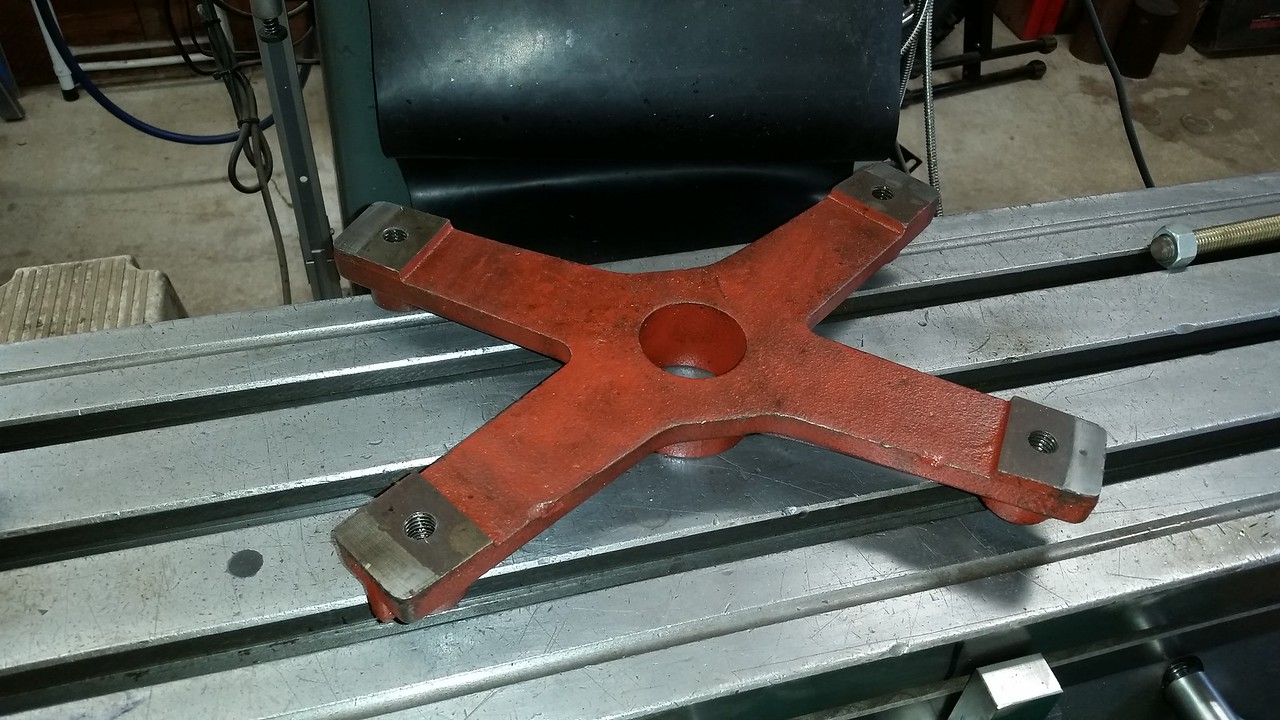
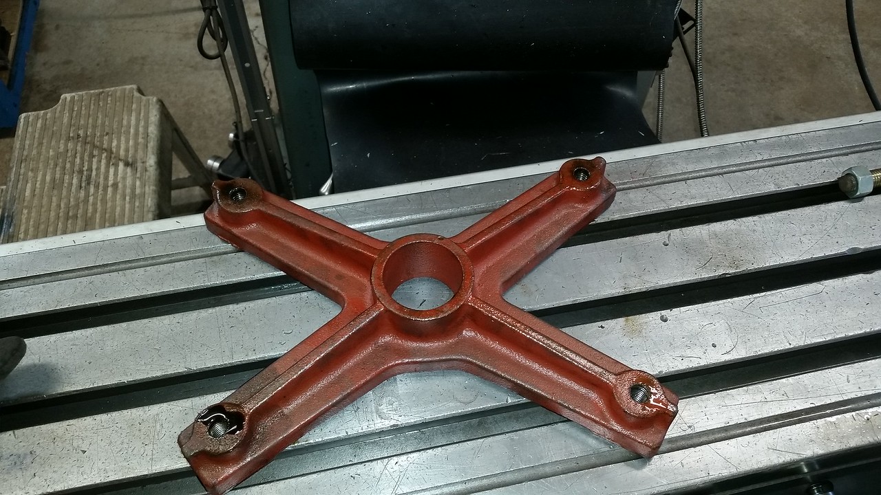
The "spider" that the ram bolts thread into looks like this.


Last edited:

Susquatch

Ultra Member
Administrator
Moderator
Premium Member
Thanks @Dabbler & @John Conroy.

I have turned down the throttle on this subproject considerably. I'm always Leary of lifting big heavy things and doubly so if they are mine! I don't need any accidents.

Ive read both your posts over several times. Most of what you say makes sense. Some doesn't.

I think I will start by watching the H&W video on disassembling the turret and base, and re-reading the turret section of the re-conditioning manual. I think it also makes sense to fabricate myself a post fixture to remove the head assembly with.

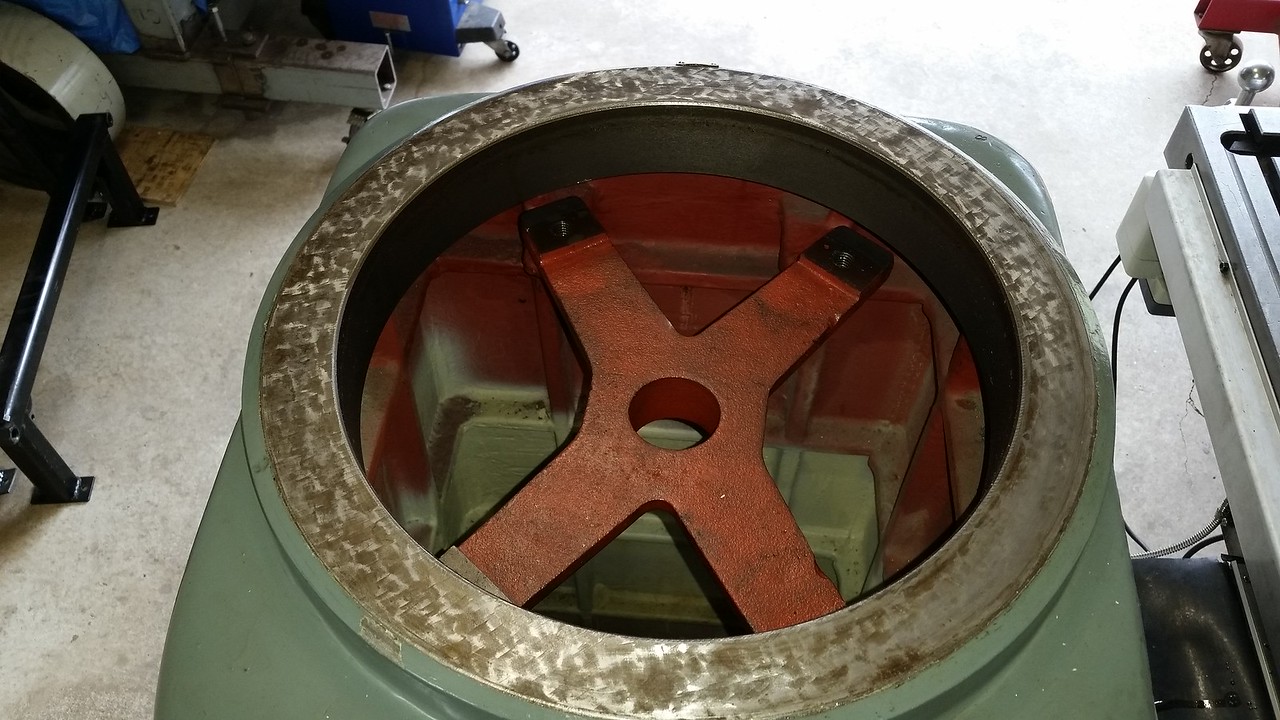
My apologies for getting the parts and process so wrong. That's what I get for jumping to conclusions. There is a door in the side of my Hartford Mill that provides access to a storage area inside the mill base. I opened the door and then took a picture of the turret mounting system from below. Here is the photo.

20210831_140937.jpg

My first mistake was to assume that the Hartford and the Bridgeport were the same.

To my eye, It looks like there are four tiny ledges in there whose only job is to hold the red bracket (spider) in place until the four turret bolts are threaded into it. Thereafter, the spider turns with the turret. But should be put back into the ledges for removal.

I do not see a threaded rod to hold things together. But tben again, it's a Hartford, not a Bridgeport. I will figure it out.

But before I do anything like that, I'll remove the motor and head. That way balance on the ram is not an issue. But regardless, I do have a leveler for my engine hoist that I can use to keep the ram level for removal and reassembly.

In regards to repairing the spider, I had assumed that it was a forging. It's a little hard to believe that they would use a casting for that. But then again...... If mine is cast iron, I may simply make an all new spider out of steel and weld on four new nuts. But that's just a thought. First I have to get it out and then take a good long hard look at it.
 

Dabbler

ersatz engineer
The only difference between the Hartford and the BP was that in the old BPs I took apart there was a central bolt/nut - but my Hartford looks exactly like the ferro that @John Conroy owns.

If the ram is retracted, the spider can be removed by taking out the 4 bolts. (I wish some told me that the first time I took apart a BP mill!)
 
Top