-
Scam Alert. Members are reminded to NOT send money to buy anything. Don't buy things remote and have it shipped - go get it yourself, pay in person, and take your equipment with you. Scammers have burned people on this forum. Urgency, secrecy, excuses, selling for friend, newish members, FUD, are RED FLAGS. A video conference call is not adequate assurance. Face to face interactions are required. Please report suspicions to the forum admins. Stay Safe - anyone can get scammed.
-
The 2026 Calgary Area Meetup is set for Saturday May 30th at 10am. The signup thread is here! Robinhood has graciously offered to host the meetup again this year. Please note that you MUST RSVP to the notice linked above if you wish to come.
You are using an out of date browser. It may not display this or other websites correctly.
You should upgrade or use an alternative browser.
You should upgrade or use an alternative browser.
New Projects New Challenges
- Thread starter carrdo
- Start date
Hi Peter,
Here are a couple of shots of the overall bender from the construction articles (Nov. 2003, Dec.-Jan. 2004 MEW). I can't send the actual construction drawings from the articles as they are marked copyright. But there are many sources for back issues of Model Engineers Workshop if the project looks to you worth undertaking.The tooling though is really something.
I made one of those, brilliant machine, quite substantial. Nothing give as smooth a small radius bend than than a mandrel bender
If convenient, I'd like to see some pics of it. Maybe a new thread because I just KNOW you have some some action shots too!I made one of those, brilliant machine, quite substantial. Nothing give as smooth a small radius bend than than a mandrel bender
Hi All,
Nothing like re-inventing the wheel!
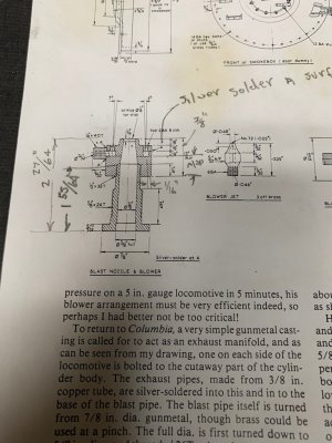
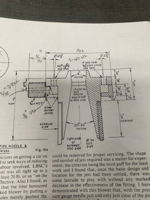
Photo 209 shows the overall blast pipe exhaust design of Laurie Lawrence which was used and modified by Martin Evans in the design of the Columbia Northern (photo 210). Laurie, subsequently, had some criticism of the Martin Evans modifications all of which are documented in the Model Engineer articles.
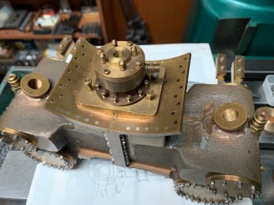
To add to all of this, I have an unknown locomotive cylinder assembly, photos 212-213, which employs a somewhat different construction technique than the preceding two designs in order to eliminate any silver soldering of the various components (i.e. an all bolted/threaded assembly).
So, to re-invent the wheel, I will employ elements, which I like, from all of the above three designs in the blast pipe assembly which I am going to make.
to be continued.
Attachments
Hi All,
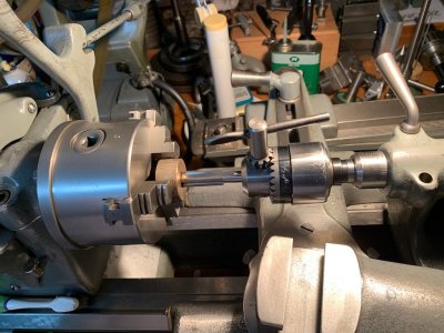
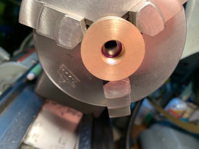
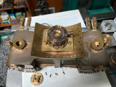
The start on the lower blast pipe assembly body. This is being made from a 1-5/16" dia. x 5/8" thick piece of bronze round bar. With the price of any metal these days, especially for a metal like solid bronze, it could have come from a jewellery store.
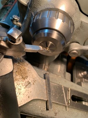
The through hole internals consist of a 1/2-32 TPI ME thread to screw on to the end of the blast pipe and a concentric 20 degree internal taper. So to be as concentric as possible after rough drilling, the thread ID section was bored to 0.468"dia. to give an 80 per cent (very close) thread engagement. The 20-22 degree included angle (as per the Laurie Lawrence drawing) was then concentric bored to this thread.
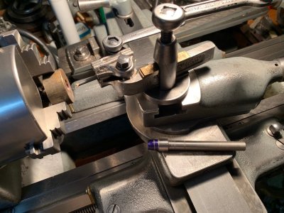
The problem was, when boring the internal taper, one could not see or measure anything that was going on at the bottom of the hole. This is critical as there has to be a smooth transition less internal taper as shown in the drawings all the way through the entire blast pipe assembly. After doing some head scratching, I came up with the inked taper plug as seen in photo 215. As boring of the internal taper proceeded, I rotated the plug against the front face of the taper hole and noted how much marking blue was being rubbed off. When the end diameter of the plug just barely showed bare bright metal, I stopped. I hope this works. We shall see.
to be continued.