• Scam Alert. Members are reminded to NOT send money to buy anything. Don't buy things remote and have it shipped - go get it yourself, pay in person, and take your equipment with you. Scammers have burned people on this forum. Urgency, secrecy, excuses, selling for friend, newish members, FUD, are RED FLAGS. A video conference call is not adequate assurance. Face to face interactions are required. Please report suspicions to the forum admins. Stay Safe - anyone can get scammed.
  • The 2026 Calgary Area Meetup is set for Saturday May 30th at 10am. The signup thread is here! Robinhood has graciously offered to host the meetup again this year. Please note that you MUST RSVP to the notice linked above if you wish to come.

New Projects New Challenges

Hi All,

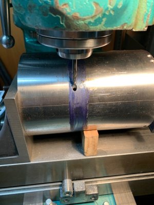
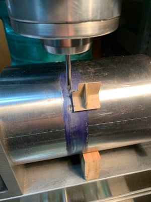
Spotting the downcomer pipe locations through the smokebox shell and glueing the cardboard aligning piece in place.

You will see in the next installment what an oblique angle one is faced with. You cannot use a regular drill here, it has to be a short and stiff center drill and short and stiff end mill(s) to make the openings.

The two black inked marks on the cardboard aligning piece are the two places which will define the angle which the centre drill and the end mill(s) must follow as they are on the centerline (at 1/2 the diameter of the locating piece at these points). Any cutter needs to be at this angle and offset from the curved shell at 1/2 of their diameter also to have the opening remain centered and coincident with (and not offset from) the original punch mark. Tricky.

to be continued.

to be continued.144 Opening Location on the Opposite Downcomer Steam Line.jpg146 The Cardboard Aligning Piece Glued in Place with Aligning Marks.jpg
 
Hi All,

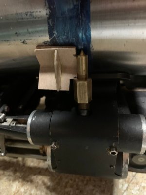
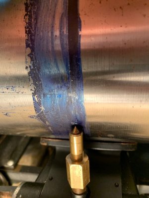
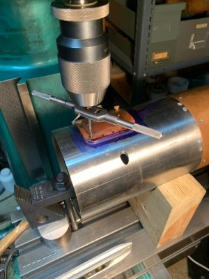
Proceeding to machine the oblique openings through the smokebox shell.

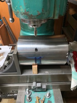
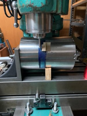
The setup to do this is shown in photo 147. Ensure everything is bolted down tight against the angle plate and cannot move at all.

The through point location on the smokebox shell always looked wrong to me so everything was checked several times before any machining was attempted.

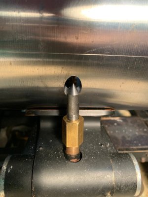
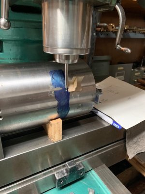
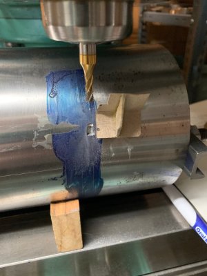
One has to create a small flat first on the curved outer shell to be able to use the extra long centre drill to make the initial break through on the shell wall. Use a very sharp small centre cutting end mill and advance the cutter very slowly and carefully. Once the initial small (3/16") through hole has been created, the cardboard aligning piece can be removed. All cutters were held in collets with the minimum extension one could get away with.

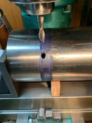
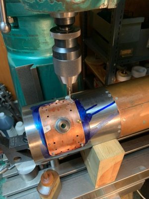
Then continue to open up the opening to its final diameter of 7/16" in small increments and plunge through very slowly using very sharp (extra long end mills if needed) two or four flute end mills. Both types will work equally well if they are sharp.

It all looks so easy from the photos but it is a very tense operation particularly at the beginning.

I also did cheat a bit. No trusting myself, at the 5/16" diameter opening stage, I marked the location of the shell on the angle plate and removed it entirely to test the hole location and angle with everything bolted in place on the chassis of the locomotive. The angle was perfect but I did have to adjust the longitudinal position of the opening a bit to have everything dead centered. Returning to the mill setup, I used a ground piece of 5/16" bar and the locating maks previously made to "pick up" where I had left off and then make the slight horizontal position adjustment.

The result, a perfectly centered and aligned opening (photo 152).

Was I ever relieved. I still have to do the other side but the procedure is exactly the same.

to be continued.
 

Attachments

  • 152 Centered and Spot on Anglewise.jpg
    152 Centered and Spot on Anglewise.jpg
    110.4 KB · Views: 9
  • 151 The Final Opening Size of Seven Sixteenths of an Inch.jpg
    151 The Final Opening Size of Seven Sixteenths of an Inch.jpg
    130.5 KB · Views: 9
  • 150 Enlarging the Opening by Plunge End Milling.jpg
    150 Enlarging the Opening by Plunge End Milling.jpg
    131.3 KB · Views: 9
  • 149 Very Careful Plunge End Milling.jpg
    149 Very Careful Plunge End Milling.jpg
    133.4 KB · Views: 10
  • 148 One has to First Create a Flat for the Centre Drill.jpg
    148 One has to First Create a Flat for the Centre Drill.jpg
    121.6 KB · Views: 10
  • 147 Picking Up the Intersection Point.jpg
    147 Picking Up the Intersection Point.jpg
    133.8 KB · Views: 10
Hi All,

The second steam downcomer opening through the smokebox shell is now finished and it came out perfect as well but again I doubted myself. Halfway through the operation I said this doesn't look right so everything was marked and removed from the mill and set back on the saddle of the two piece cylinders, the smokebox shell locked in position and the downcomer steam pipe centre point on the shell and the cardboard aligning piece verified as to the correct angle when set against the custom made dummy pointed downcomer pipe pieces as seen in photo 152.

Then reassemble everything on the mill and the position and angle was exactly as before! I couldn't believe it. It looked wrong.

Just a few more notes to clarify things.

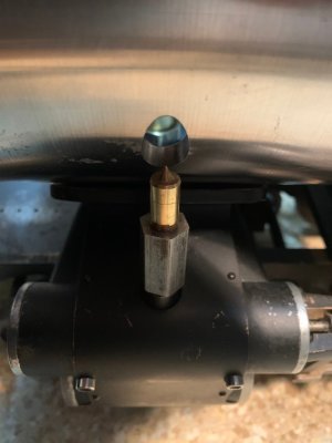
The custom made straight pointer in photo 153 is aligned to the two black marks on the cardboard aligning piece. These marks have been created when the cardboard aligning piece is set against the dummy downcomer pipe pieces as seen in photo 152 and when the cardboard aligning piece is glued to the shell of the smokebox. The end of the pointer picks up the layout punch mark which is the centre of the oblique opening. Also, the shell itself is rotated until the two black marks are 1/2 the diameter of the pointer or are on the center of the pointer thickness wise. Some fiddling is needed here to satisfy both these conditions. Then everything is locked. This will ensure that all of the subsequent plunge end milling operations are centered and located correctly (photo 154).

One further point and I am not certain if this is relevant or not.

The smokebox shell is clamped in the upside down position for all of these operations and the shell is also turned end to end when doing the opposite side. If this is not done I think one of the openings can be in the right position but with a reversed oblique opening but I am not certain about this. One has to think here about how each downcomer pipe comes from the cylinders and up into the smokebox through the smokebox wall. Think about this before cutting any metal.

to be continued.
 

Attachments

  • 153 The Two Black Marks on the Cardboard Aligning Piece Must be at One Half of the Diameter of...jpg
    153 The Two Black Marks on the Cardboard Aligning Piece Must be at One Half of the Diameter of...jpg
    121.6 KB · Views: 5
  • 154 Plunge End Milling the Initial Flat.jpg
    154 Plunge End Milling the Initial Flat.jpg
    111.5 KB · Views: 5
  • 156 Centered and Spot on Anglewise.jpg
    156 Centered and Spot on Anglewise.jpg
    73 KB · Views: 6
Hi All,

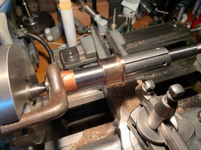
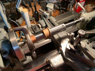
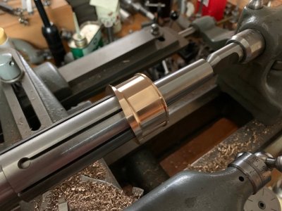
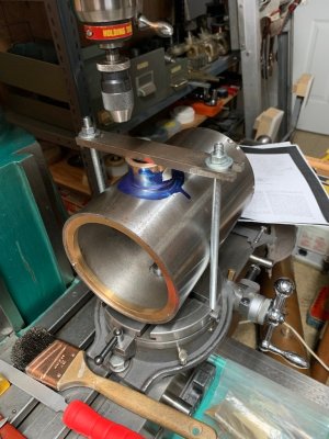
Am finally back to undertaking some finishing work on the stack casting. This operation involves profiling the OD of the stack with some very basic form tools to form the root radii on the stack upper and lower flanges. I can only do this by employing the fancy expanding arbor as seen in the setup photo (photo 157).

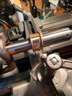
I had to proceed very slowly and take very light cuts as I left the casting only a light tap fit on the expanding arbor sleeve (with the sleeve left slightly recessed on the upper flange end) due to the fact that I also wanted to face across the top flange square to the bore and to the outer profile. Many times this resulted in slippage if I took too heavy a cut, so one had to carefully retap the sleeve/casting numerous times.

The other problem which resulted was chatter when forming the upper and lower flanges (the root radii) as the form tool starts to cut all around its profile. Sometimes, one had to resort to hand turning the chuck to eliminate this chatter using only very light scraping cuts with the sharpest cutter. This is where any looseness anywhere will come back to bite you.

to be continued.
 

Attachments

  • 159 The Roughed Out Stack OD Profile.jpg
    159 The Roughed Out Stack OD Profile.jpg
    159.5 KB · Views: 11
  • 158 Taking Very Light Cuts.jpg
    158 Taking Very Light Cuts.jpg
    154.6 KB · Views: 10
  • 157 The Setup to Turn the OD Stack Profile.jpg
    157 The Setup to Turn the OD Stack Profile.jpg
    172 KB · Views: 12
That turned out well.
I actually bought a single expanding arbor sleeve when I was building my radial, single because they are kind of spendy as graduated sets. Fuzzy memory but I'm pretty sure from KBC Tools. When I put a DTI on the mated assembly the runut was not very good, I'll say 0.003" just off the top of my head. I removed the outer sleeve & measured inner part, seems like it was about half. The enter drills looked unremarkable, re-mounted & got exact same readings. So something not right about concentricity relative to center drills. I maybe could hav edialed it in better with a 4J chuck but I think thats going outside their intended setup on centers? I returned it & have been kind of cool on them since. Now they do stock low level stuff too so maybe that was the issue. Anyway, what brand is yours & what kind of TIR do you get?
 
Hi Peter,

You got me on this. I simply don't know as I have not tested the concentricity or runout as this was the first job where they were used. Locomotive work, especially on something like this, does not have the same precision requirements as does IC work so if the runout was 0.003", no one will notice and it won't affect the operation of the locomotive. And yes, I could have had runout as I held the stack casting very lightly on one end of the expanding arbor sleeve. The sleeve was not pressed on hard as one could do if one was turning, say, a heavy IC flywheel. The stack part ended up being a relatively thin shell after profiling and I was afraid that I might split the casting if I pressed the expanding sleeve hard on the tapered arbor.

There is no name on the set which I purchased on ebay so I presume they are nothing special and from offshore but there was nothing obviously wrong when inspected visually. Everything appears to be hardened. The price was quite reasonable as I bought a set which was missing a size and yes, I have seen individual expanding arbor sleeves which were three times the price of what I paid for the entire set here (I received 6 out of a seven sleeve set). I do have sizes now from 1/2" up to 2" which will cover anything I ever expect to need.
 
I had the same experience with a made in India MT reference bar. The OD & taper was very accurate because of centerless grinding. But it was way off if registered on center pips. My thinking was they used the centers to rough turn the blank but bever utulized again for centerless grinding, so basically not intended to be used that way. Maybe the 'real' bars are different, I really dont know.

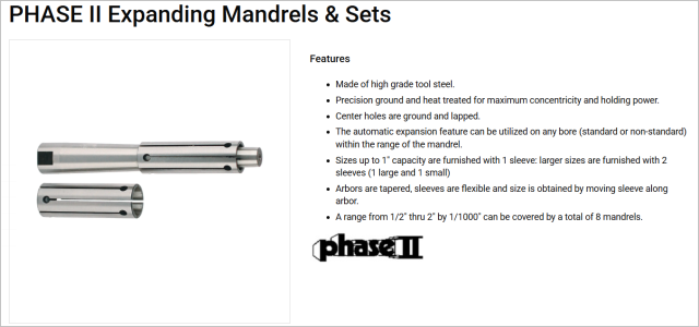
Back to expanding mandrels, forexample Travers only carries one line, Phase II, the house brand usually from Asia. QC kind of varies from totally acceptable to something less from my experience

The description says center holes are ground & lapped which I do not recall being stated on KBC line. Maybe an inprovement? But that could be then vs now or the offshore line they carried at the time. The outer sleeve is hardened so these are not intended to be skimmed in-situ. I think you get what you get.
1784389091647.png
 
Hi All,

The start of my secret "riveting" process to rivet the stack to the smokebox shell. Only you guys are ever going to see this.

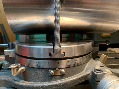
The first operation is to make a very close fitting (a tap fit) plug to fit into the blast pipe opening which is exactly opposite the stack opening in the smokebox shell (photo 164). This plug fits the shown centering piece of my rotary table.

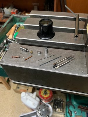
The next operation is to make custom threaded rivets from commercial 1/16"diameter model engineering rivets. All of the special parts to do this (including the nuts) are shown in photo 165. The plain rivets are threaded 0-80 NF. It is quite a fiddle to handle all of these tiny pieces.

to be continued.
 

Attachments

  • 164 The Very Close Fitting Plug in the Blast Pipe Opening.jpg
    164 The Very Close Fitting Plug in the Blast Pipe Opening.jpg
    186.5 KB · Views: 10
  • 165 The Custom Made Tooling Used to Thread the One Sixteenth Inch Rivets and the Rivet Nuts.jpg
    165 The Custom Made Tooling Used to Thread the One Sixteenth Inch Rivets and the Rivet Nuts.jpg
    130.8 KB · Views: 9
Last edited:
Hi All,

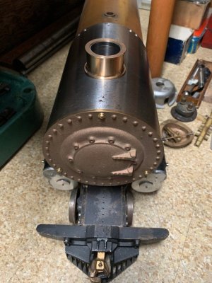
The smokebox shell as setup on the centered rotary table (photos 166 167). As you can see, I was pushing the limits of what my 6" diameter rotary table can handle.

I was just about to tilt the head of the mill a few degrees to provide clearance for the rivet drilling operation when I realized there was a big problem. This operation had worked fine on previous locomotive projects but it wasn't going to work on this one. I should have seen this much earlier but I didn't.

The stack bottom curved flange which sits on the smokebox shell, when turned from the casting provided, ended up being much smaller than on previous models due to a casting flaw which I wanted to get rid of. The resultant smaller bottom flange looked very good aesthetically, but then I realized the rivet drilling operation would drill into the stack liner itself making my "easy/practical" method of assembly/disassembly, if ever needed, not possible.

The Columbia design does show the stack "mechanically attached" as either a riveted or bolted assembly (no details given) but on a much wider flange.

So, as a result, I decided to go with the easiest alternative route of using a high temperature adhesive such as Loctite 620 on the underside of the stack bottom flange. This adhesive has a upper heat limit of 450 degrees F. which the stack will never reach but if it ever does then I am looking at silver soldering the stack/ss liner assembly. This adhesive also has the advantage of being listed as a strong sealing adhesive which the smokebox needs as there can be no leaks whatsoever of air into the smokebox. The smokebox needs to always be under a slight negative pressure when the locomotive is operating in order to draw the firebox combustion gases through the boiler tubes.

to be continued.
 

Attachments

  • 168 The Installed Stack.jpg
    168 The Installed Stack.jpg
    146.8 KB · Views: 6
  • 167 Employing Adjustable Parallels to Level the Smokebox Shell.jpg
    167 Employing Adjustable Parallels to Level the Smokebox Shell.jpg
    156 KB · Views: 6
  • 166 The Smokebox Shell Setup on the Rotary Table.jpg
    166 The Smokebox Shell Setup on the Rotary Table.jpg
    154 KB · Views: 6
Hi All,

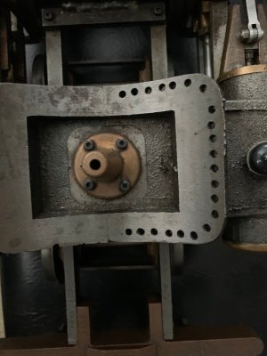
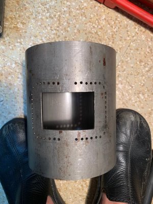
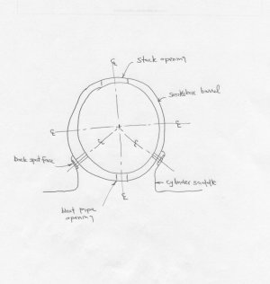
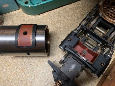
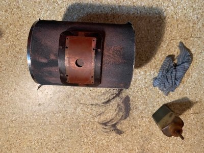
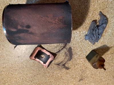
Next up is to attach the smokebox shell to the cylinder saddle with drilled matching holes in each part as seen in photos 170-171. These photos are taken from another project and are used here only for illustration. Photo 172 is a cross section sketch showing their location in relation to other smokebox features.

Don't be fooled, this is one of the most demanding and intense operations one can get into as I will explain.

To begin with there is no way that these two parts can be drilled together. One has to first carefully lay out and drill the cylinder saddle bolt hole locations first and then spot each one through on to the smokebox shell so that each and every hole in both parts aligns perfectly. Not only that but one has to be aware of and perfectly align every other feature which has previously been machined into the smokebox shell. In my case I am also going to flush thread the saddle bolts directly into the smokebox shell, so the room for error, this way, is even smaller (just the clearance drill size on each bolt hole). I want to have as clean and clear a smoke box interior as possible. Why, because the smoke box shell will house the internal poppet multi valve throttle, the superheater header(s), the two steam downcomer pipes, the multi nozzle blast pipe assembly, the blower ring and blower piping, etc. and yet it is still necessary to thread one's way past all of these obstructions to be able to clean and brush out all of the boiler tubes and flues on a regular basis. It is a totally contradictory situation but every bit of clearance you can find helps. As you can see there is no lack of things yet to be made.

Not only that but in order to even begin this operation, I have to remove the cylinders from the locomotive chassis and their motion works, strip it down to a bare cylinder block, mark everything, then reset the bare block square, level and aligned in every direction on the table of the mill. This in itself is hours and hours of patient frustrating additional work. And you cannot make a mistake at any point in the process.

This is where preparation and setup is everything. I am in the midst of this at the moment so stay tuned.
 

Attachments

  • 170 A Cylinder Saddle with Partially Drilled Bolt Holes.jpg
    170 A Cylinder Saddle with Partially Drilled Bolt Holes.jpg
    113.9 KB · Views: 3
  • 171 A Smokebox Shell with Drilled Bolt Holes.jpg
    171 A Smokebox Shell with Drilled Bolt Holes.jpg
    149.8 KB · Views: 3
  • 172  My Original Sketch on the Layout and Drilling of the Cylinder Saddle and Smokebox Shell ...jpeg
    172 My Original Sketch on the Layout and Drilling of the Cylinder Saddle and Smokebox Shell ...jpeg
    55.5 KB · Views: 3
Last edited:
Hi All,

Well, this locomotive gave me a real surprise. And unlike what I normally experience, it was a very pleasant one.

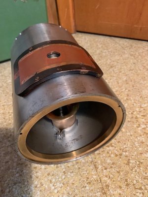
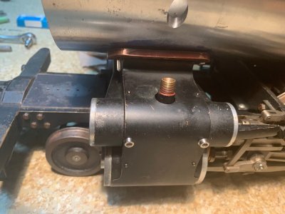
When I began to look at how best to remove the cylinders from the locomotive chassis, I discovered it had a detachable saddle piece! Not only that, it is a complete one piece cylinder block unlike the normally seen two piece split half cylinders. I have not encountered this before so It came as quite a surprise.

This means that it will be very easy to attach both parts together with no fancy setup's or special aligning fixtures to make. And the remaining nearly complete cylinder assembly does not have to be removed from the chassis saving all that work and aggravation. Whoever designed this and had it cast this way (no easy task) was really using his noggin.

The only thing I struggled with a bit was to remove the four saddle piece flat head retaining bolts which were standard shallow slotted. Two of these fasteners were more or less destroyed getting them out so I replaced all of them with standard flat head cap screws as seen in the photo.

to be continued.
 

Attachments

  • 181 The Cylinders Have a Detachable Saddle Piece.jpg
    181 The Cylinders Have a Detachable Saddle Piece.jpg
    194.3 KB · Views: 10
Hi All,

One final operation before the trial fitting the saddle piece to the smokebox shell.

The smokebox saddle piece was a close fit on the smokebox outer shell but I wanted it even closer without having to go through the entire setup process again.

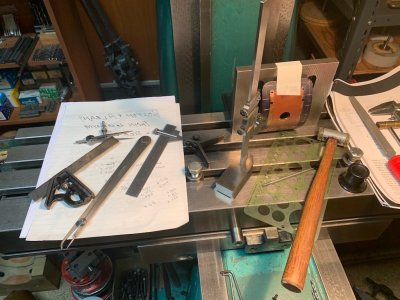
I came up with the quick and dirty method shown in the photos. A piece of coarse emery paper was tightly duct taped around the outer shell and the curved underside of the saddle piece was translated and oscillated around on it dry. Very crude but it worked as the saddle piece now fits the outer curve perfectly. Just take your time and press lightly.

to be continued.
 

Attachments

  • 182 Coarse Emery Paper Duct Taped to Smokebox Shell.jpg
    182 Coarse Emery Paper Duct Taped to Smokebox Shell.jpg
    220 KB · Views: 3
  • 183 After Grinding In The Cylinder Saddle Piece.jpg
    183 After Grinding In The Cylinder Saddle Piece.jpg
    228.3 KB · Views: 3
  • 184 Now a Very Close Fit.jpg
    184 Now a Very Close Fit.jpg
    119.7 KB · Views: 3
Hi All,

Continuing on. Contrary to my previous assertion, even having a detachable cylinder saddle piece there is no easy way to attach the cylinder saddle piece to the smokebox shell and have all of the existing features align including the cylinder saddle piece/smokebox shell bolts. As far as I can tell, both pieces have to be drilled independently with one spotted through from the other. And it all has to be done perfectly.

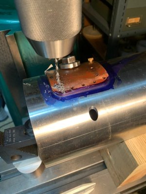
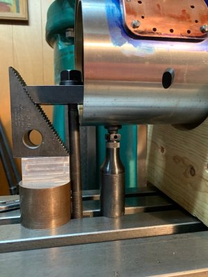
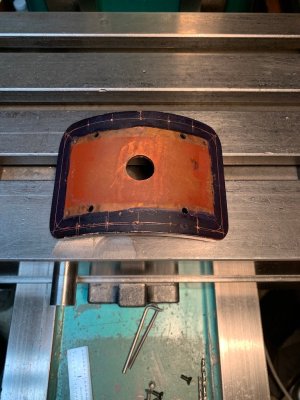
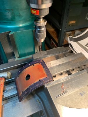
So, the first operation was to layout and drill all of the mounting holes in the cylinder saddle piece. See the attached photos.

These will all be clearance holes (#27 drill) for the attachment bolts which are 6-32 NC threaded. These holes all need to be drilled radially (i.e. exactly at 90 degrees) at each hole location on the saddle piece curve (which is the arc of a circle). And since I decided to do this more or less by eye, it had consequences later which needed a workaround.
 

Attachments

  • 178 Laying Out the Bolt Holes on the Cylinder Saddle Piece.jpg
    178 Laying Out the Bolt Holes on the Cylinder Saddle Piece.jpg
    159.3 KB · Views: 7
  • 179 After Laying Out.jpg
    179 After Laying Out.jpg
    156.1 KB · Views: 6
  • 180 Drilling the Bolt Holes.jpg
    180 Drilling the Bolt Holes.jpg
    145.8 KB · Views: 6
Hi All,

Next up was to assemble all of the various components on the locomotive chassis. But first, the smokebox shell was thoroughly covered with layout dye in the entire general area of the cylinder saddle. The cylinder saddle itself was then attached and mated to the main cylinder casting by the four flat head mounting screws which is how the two components were originally attached together.

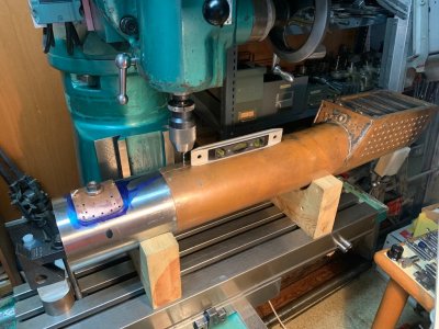
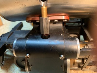
Then the smoke box shell was attached to the boiler via the 12 flat head existing mounting screws which secured these two components together and the assembly was then mounted on the locomotive chassis in its final position. After that I attached the threaded blast pipe from the cylinders through the closely fitting blast pipe opening in the smokebox shell. All of this required some slight adjustment to achieve the necessary fits but was absolutely vital to setting the attachment bolt holes locations. After all of the features were checked to ensure they were in their final correct position, I carefully scribed the outline of the cylinder saddle on the smokebox shell followed by spotting through the four corner cylinder saddle attachment bolt hole locations using a custom made sharp pointed and close fitting (clearance hole size) spotting plug. I also made a custom drill guide as seen in photo 188, the purpose of which was to guide and align the drill radially when drilling through into the smokebox shell itself. This was necessary as you will see.

Now for the crazy part. In order to preserve all of this vital alignment as much as possible, I had to heave the entire boiler/smokebox/cylinder saddle assembly up on to the table of the milling machine as a one piece unit. To say that this was "fun" well... it was really a 2-3 person operation (photos 189-90) and too big for the mill. Somehow I did it but it needed preparation in every detail. As can bee seen in the overall setup photo, the boiler needed to be set as level as possible and securely clamped and supported at the smokebox end as the entire mess had to be rotated by hand to bring each of the drilled cylinder saddle holes into position. Hence the need for the custom drill guide to guide the tapping drill when drilling through into the smokebox shell.

To be certain that I was aligned as close as possible, I could just see the entire scribed saddle outline on the marking blue on the smokebox shell and if one shone a light down through the saddle piece corner clearance holes, one could see that the spotting through marks were centered in the holes (or as close as I could determine that they were). In addition, the close fitting threaded blast pipe opening plug/clamp I made as seen in photos 189 and 191 is needed to clamp the cylinder saddle to the smokebox shell and help align the cylinder saddle piece.

Even with all of this, could I be certain that everything would align? It had to be perfect and was it? - I still didn't know - it was a real tense moment.

to be continued.
 

Attachments

  • 192 First Tapping of the Smokebox Shell.jpeg
    192 First Tapping of the Smokebox Shell.jpeg
    129.2 KB · Views: 4
  • 191 First Drilling Through the Smokebox Shell.jpeg
    191 First Drilling Through the Smokebox Shell.jpeg
    122.4 KB · Views: 3
  • 190 Clamping and Supporting the End of the Smokebox Shell.jpg
    190 Clamping and Supporting the End of the Smokebox Shell.jpg
    122.7 KB · Views: 4
  • 189 The Overall Setup for Drilling and Tapping the Cylinder Saddle to the Smokebox Shell.jpg
    189 The Overall Setup for Drilling and Tapping the Cylinder Saddle to the Smokebox Shell.jpg
    165.5 KB · Views: 5
  • 188 The Custom Made Hollow Drilling Sleeve for Drilling Into the Smokebox Shell.jpeg
    188 The Custom Made Hollow Drilling Sleeve for Drilling Into the Smokebox Shell.jpeg
    79.2 KB · Views: 6
Hi All,

Each of the four corner bolt holes was then rotated into position and the smokebox shell was drilled and tapped through. If the four corner holes were right then all of the remaining holes could be drilled and taped without concern.

The moment of truth had arrived. Everything was taken off the mill and re-assembled.

My custom made 6-32 NC attachment bolts would not thread in (!!) but I could see that they were very close. I had some old commercial well worn threads and they would partially thread in. As well, the tapping drill would easily pass right through each of the holes. So what was the problem and what to do?!

In situations like this, sometimes the answer comes out of the blue and sometimes it doesn't. Then it hit me. The evidence was telling me both sides of the holes were coincident but not exactly radial as I had aligned the cylinder saddle clearance holes by eye.

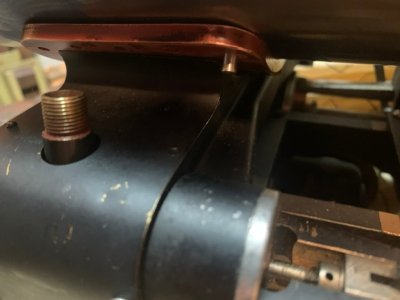
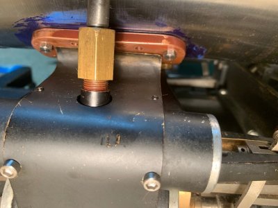
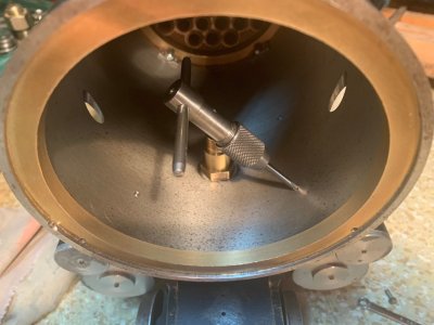
The answer was to reverse tap back down the threaded portion in the smokebox shell as seen in photos 194-195. I could feel that the threading tap was just touching a part of the wall of each clearance hole as the tap went through confirming what I suspected. After reverse threading, the commercial threads (they were fully threaded) went straight through but my custom made bolts (which were partially threaded) would start but not fully thread in. The final answer was to turn them down from their nominal OD of 0.138" to 0.135" when they would thread through all of the way. No one will know the difference.

As they say in the UK, I am chuffed (and incredibly relieved) that this is now all behind me.

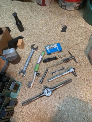
PS1: In such a restricted space as here, open end or adjustable wrenches are to be avoided as you will destroy the hex head attempting to use them. Snap-On (and perhaps others do as well) make a series of 6 point miniature ignition box end wrenches which are necessary to properly install and remove these types of miniature mild steel hex bolts. I have them from 1/8" to 1/4" in 1/32" increments. The Snap-On ones are not cheap but If you do any type of model work..

PS2: If any of you have any ideas about a better way of doing the above, then I am all ears. I did consult another all Live Steam builders web site asking the same question and what answers I received were a variation of what I have described so...
 

Attachments

  • 197 The Many Tools Needed for the Fitting.jpg
    197 The Many Tools Needed for the Fitting.jpg
    255.1 KB · Views: 5
  • 196 The Cylinder Saddle Corner Bolts Final Fitted Into the Smokebox Shell.jpg
    196 The Cylinder Saddle Corner Bolts Final Fitted Into the Smokebox Shell.jpg
    111.5 KB · Views: 5
  • 195 Reverse Tapping Through the Smokebox Shell.jpg
    195 Reverse Tapping Through the Smokebox Shell.jpg
    108 KB · Views: 5
  • 194 Reverse Tapping Through the Smokebox Shell for Final Fitting of the Corner Attachment Bolts.jpg
    194 Reverse Tapping Through the Smokebox Shell for Final Fitting of the Corner Attachment Bolts.jpg
    100.9 KB · Views: 4
  • 193 Third Drilling of the Smokebox Shell.jpeg
    193 Third Drilling of the Smokebox Shell.jpeg
    131 KB · Views: 5
Hi All,

After finally successfully bolting the cylinder saddle through into the smokebox shell, I could now proceed with all new construction without regard to first having to align the many existing smokebox shell features which caused so much grief. At least, that is what I thought!

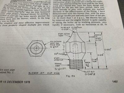
I decided next to proceed with the blower ring itself. It has four blower ring jets as seen in photo 201. In the drawing, because it is enlarged, they appear to be quite straight forward to produce. Not so! They are tiny with the jet section of the blower ring itself being a drilled #80 drilled hole.

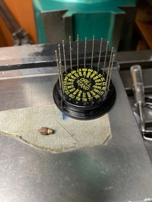
I have never drilled with a #80 drill before and all I can say is that it is a different animal. I have successfully drilled down to #63 holes but this is really different; one has trouble even handling the drill. To begin with no ordinary Jacobs type drill chuck can correctly hold such a small drill; fortunately, I have a 0-1/8" Albrecht chuck but even this is not ideal. Albrecht makes a special, super sensitive, design 0-1/16" drill chuck for these tiny drills and that is what is needed.

To compound the problem, feeding the drill directly with the tailstock hand wheel (on the 9" SB lathe as I had no other method at the time) is a no-no. I snapped the drill off when when feeding it this way even being exceptionally careful with peck drilling minute amounts and clearing chips. The drill jammed in the partially drilled hole and that was it - part scrapped. I know that one can alter the drill cutting lips on a stone to a zero cutting rake when drilling brass but try that on a #80 drill even under magnification. I was learning the hard way again.

to be continued.
 

Attachments

  • 200 All Bolted Together.jpg
    200 All Bolted Together.jpg
    105.5 KB · Views: 5
  • 201 Blower Ring Jet Drawing.jpg
    201 Blower Ring Jet Drawing.jpg
    167.8 KB · Views: 7
  • 202 My First Failed Attempt.jpg
    202 My First Failed Attempt.jpg
    140.3 KB · Views: 6
Last edited:
I have never drilled with a #80 drill before and all I can say is that it is a different animal. I have successfully drilled down to #63 holes but this is really different; one has trouble even handling the drill. To begin with no ordinary Jacobs type drill chuck can correctly hold such a small drill; fortunately, I have a 0-1/8" Albrecht chuck but even this is not ideal. Albrecht makes a special, super sensitive, design 0-1/16" drill chuck for these tiny drills and that is what is needed.
To compound the problem, feeding the drill directly with the tailstock hand wheel (on the 9" SB lathe as I had no other method at the time) is a no-no. I snapped the drill off when when feeding it this way even being exceptionally careful with peck drilling minute amounts and clearing chips. The drill jammed in the partially drilled hole and that was it - part scrapped. I know that one can alter the drill cutting lips on a stone to a zero cutting rake when drilling brass but try that on a #80 drill even under magnification. I was learning the hard way again.
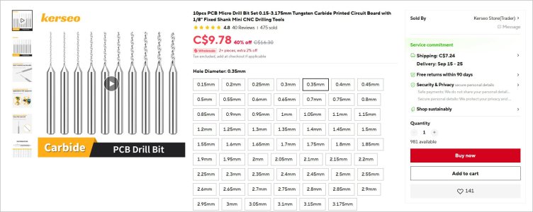
#80 is 0.0135" or ~0.34mm. Have you tried tungsten carbide PCB drills? I find they work well & have a larger shank diameter which eliminates the need for a special (small) 3J chuck. Pecking is usually the way to do it but the real problem I see with a tailstock driven drill is if your TS is positioned left or right 0.001", that represents 7.4% of diameter. Most all TS are positioned high 1-2 thou unless you have taken yours down. Now add it any runout of whatever you used to hold the tiny drill & very rapidly errors accumulate & it usually ends badly. If you manage to get a hole, its probably not aligned to center or consistent diameter. That mat not be of consequence in this application if its ?pressure relief? or something.

Have you ever measured runout of your Albrecht? Is it the fixed jaw to shank model or the in & out sensitive feed model? I'm curious because I have one too. It appeared to be brand new but actually not that amazing TIR wise. I'd have to pull up my numbers but why I went to PCB drills in a larger chuck I know is under 0.0005"
 

Attachments

  • SNAG-05-09-2026 8.51.15 AM.jpg
    SNAG-05-09-2026 8.51.15 AM.jpg
    218.9 KB · Views: 3
I looked up a couple of rpm recommendations for #80 bit and brass,, 60,000ish rpm and a 118 degree grind. That's an insane speed and a grind that would only be done at the factory.
Almost be worth paying someone with the right equipment to do those ones.
 
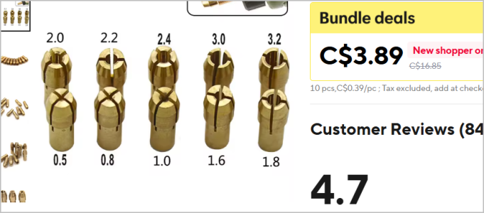
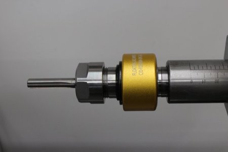
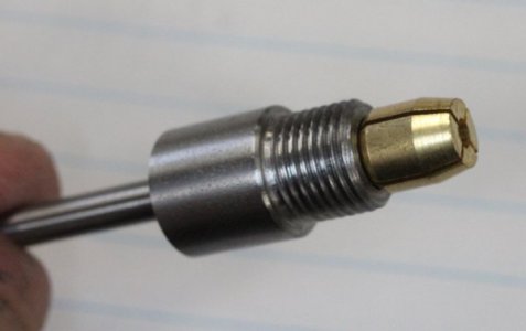
Another project on my list. You can get these Chinese brass collets cheap. (Hint dont buy them for a N-Am Dremel or Milwaukee rotary tool, the taper & shank diameter is different. Must be made for a metric rotary tool). I'm not sure how small a diameter they go, I just pulled a randon picture. I did some testing holding a pin in a 5C collet which I knew was accurate. The TIR is actually respectable. If you made you own holder & (accurately) & use their threaded cap, you basically have a small diameter drill chuck which IMO will hold better than jaws. I made something similar for a high speed rotary tool which was kind of a fail for other reasons, but its within the range of what a model engineer can accomplish.

Also forgot to mention, back to your TS, I wonder if a floating reamer holder would help? You still have to have an accurate spot drill, but thats easy

1788620612493.png
 

Attachments

  • 25032503.jpg
    25032503.jpg
    16.1 KB · Views: 1
  • IMG_5243_edited-1.jpg
    IMG_5243_edited-1.jpg
    20.8 KB · Views: 1
Back
Top