• Scam Alert. Members are reminded to NOT send money to buy anything. Don't buy things remote and have it shipped - go get it yourself, pay in person, and take your equipment with you. Scammers have burned people on this forum. Urgency, secrecy, excuses, selling for friend, newish members, FUD, are RED FLAGS. A video conference call is not adequate assurance. Face to face interactions are required. Please report suspicions to the forum admins. Stay Safe - anyone can get scammed.
  • The 2026 Calgary Area Meetup is set for Saturday May 30th at 10am. The signup thread is here! Robinhood has graciously offered to host the meetup again this year. Please note that you MUST RSVP to the notice linked above if you wish to come.

New Projects New Challenges

Hi All,

To finish up with the petticoat casting machining.

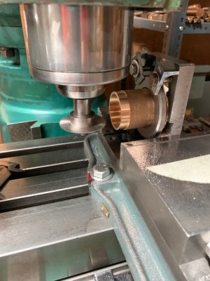
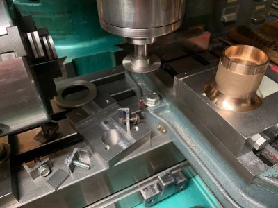
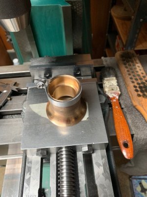
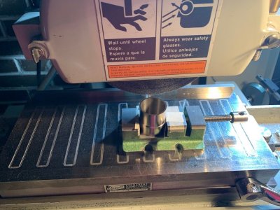
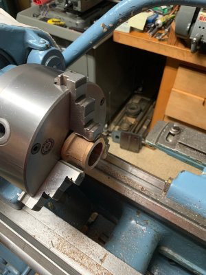
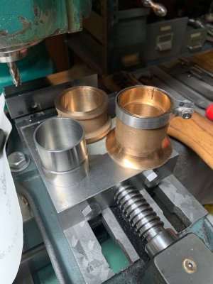
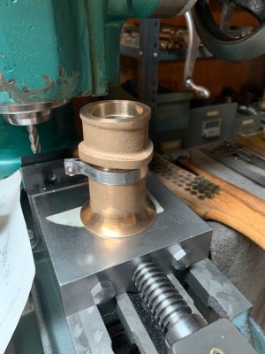
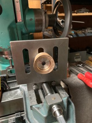
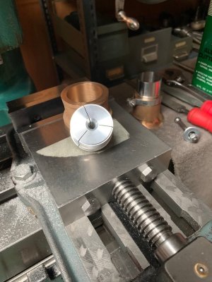
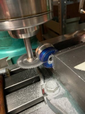
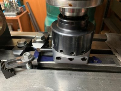
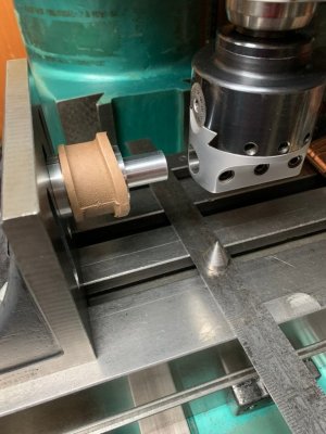
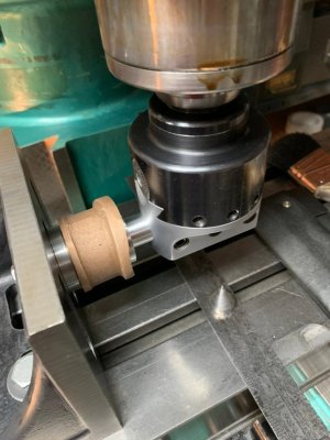
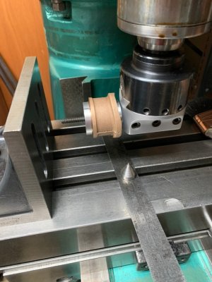
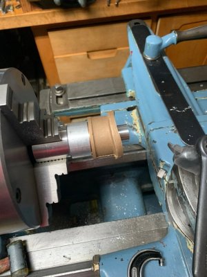
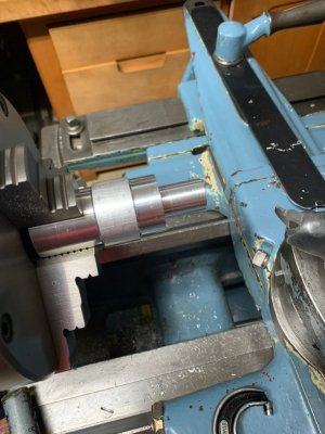
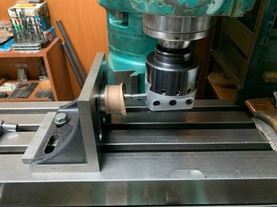
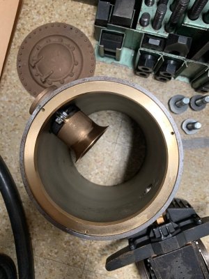
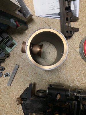
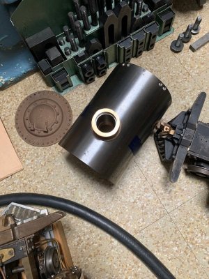
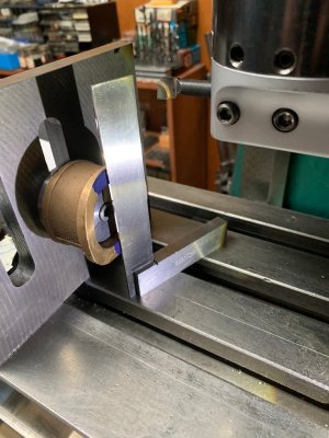
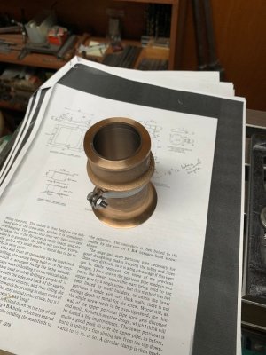
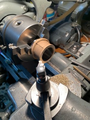
The final operation was to slit the clamp ring section (one wall only) of the casting approx. 0.015" and 1/2" deep with the appropriate size slitting saw as shown in photo 81. I don't think I need to go into all of the details regarding how to set this up so that the slitting saw is exactly on the centerline of the part, but if anyone needs an explanation I can provide it with photos.

to be continued.
 

Attachments

  • 81 Slitting the Clamp Ring.jpg
    81 Slitting the Clamp Ring.jpg
    142.6 KB · Views: 15
  • 83 The Finish Machined Petticoat Casting.jpg
    83 The Finish Machined Petticoat Casting.jpg
    136.1 KB · Views: 16
Hi All,

Moving on to making the stainless steel strap for the petticoat. This involves a type of metal forming which I have never done before. I have done lots of metal bending but not this type of a forming operation.

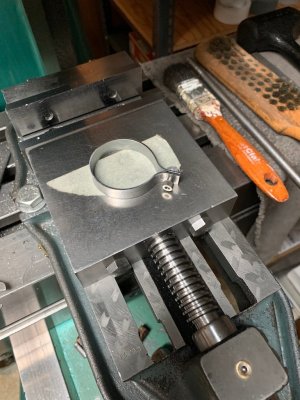
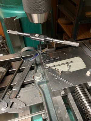
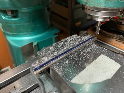
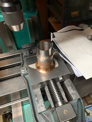
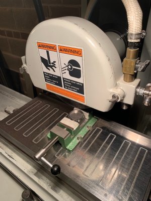
Anyway, when milling long thin strips, one needs to pay special attention to the clamping and the thin strip support as shown in photo 84. Full length clamping and support right up to the edge to be milled is needed here otherwise the edge will bend under the milling forces encountered. One also needs to calculate beforehand the required strip straight length (which I didn't as I only had a fixed length of 303 stainless steel sheet but it turned out to be exactly what was needed).

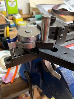
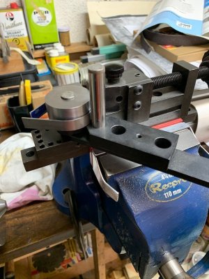
Forming the strap piece itself was all new. The metal former which is seen in the photos had instructions/photos which somewhat showed what was involved but not exactly for the type of strap (although it did show a picture perfect example of what I wanted).

In preparation, I had machined up a custom size round steel former as seen in photos 85-86 which was made 0.010" smaller in diameter to compensate for any metal springback (which in retrospect turned out to be much more (in the order of 3/32"-1/8").

The forming itself was made by centering and clamping the strip in the middle and forming out from the centre reversing the strip as necessary. The bent straight end tabs, I couldn't figure out how to do it in the bender so they were bent manually with pliers and protective wood strips to prevent marring the metal. Then I sort of changed the setup to that seen in photo 86 and it sort of formed the tab root radius but was this the correct way to do it ???

If someone else has done this, I would be very interested in seeing any photos of how it was done by your method(s).

In the end the strap clamp turned out fine (photo 89) so maybe it was beginners luck.

After drilling and tapping for the clamp screw, it was tested on the petticoat casting and it clamps perfectly all of the slack being taken up as the screw is tightened.
 

Attachments

  • 90 The Finished Petticoat Liner Clamp Strap.jpg
    90 The Finished Petticoat Liner Clamp Strap.jpg
    136.6 KB · Views: 16
  • 89 The Finished Formed Clamping Strap.jpg
    89 The Finished Formed Clamping Strap.jpg
    152.8 KB · Views: 14
  • 88 Tapping the Strap Clamp Screw.jpg
    88 Tapping the Strap Clamp Screw.jpg
    159.1 KB · Views: 10
  • 86 Further Forming.jpg
    86 Further Forming.jpg
    120.8 KB · Views: 8
  • 85 Forming the Stainless Steel Strap Clamp.jpg
    85 Forming the Stainless Steel Strap Clamp.jpg
    149.4 KB · Views: 8
  • 84 The Setup for Milling the Thin Stainless Steel Strap Piece.jpg
    84 The Setup for Milling the Thin Stainless Steel Strap Piece.jpg
    165.4 KB · Views: 17
Last edited:
Hi All,

Moving on with the internal taper boring of the stack liner.

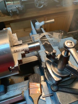
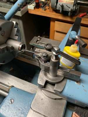
Boring the 304 stainless was no fun as the boring tool whether HSS or a brazed carbide had to be kept razor sharp to even have a chance with this alloy. It quickly dulled both. The material would start to squeal, it produced long thin razor sharp stringy chips and would ball up at the cutting edge of the boring bar leaving a ragged cut and making in feed difficult. It also heated up the blank after a pass or two. I basically lost 3 boring bars to this operation. I know there are now specialty inserts which are specifically designed for this type of stainless but I don't have any (the make or grade) so...

In the end I got there with a new razor sharp brazed carbide bar as seen in photo 94 (for the final finish pass only). One can now run one's finger down into the smooth internal bore of both parts and not feel any transition between the petticoat and the internal liner.

to be continued.
 

Attachments

  • 93 Boring the Stack Liner Internal Taper.jpg
    93 Boring the Stack Liner Internal Taper.jpg
    148.3 KB · Views: 5
  • 94 The Completed Stack Liner Internal Boring.jpg
    94 The Completed Stack Liner Internal Boring.jpg
    155.7 KB · Views: 6
  • 95 The Stack Liner and the Petticoat Casting.jpg
    95 The Stack Liner and the Petticoat Casting.jpg
    102.9 KB · Views: 6
Hi All,

Finishing the stack liner. This involved straight forward turning, facing and fitting operations so little comment.

to be continued.
 

Attachments

  • 100 The Stack Liner Projecting Through The Smokebox Shell.jpg
    100 The Stack Liner Projecting Through The Smokebox Shell.jpg
    159.5 KB · Views: 5
  • 99 First Setting in the Smokebox Shell.jpg
    99 First Setting in the Smokebox Shell.jpg
    84.9 KB · Views: 4
  • 98 The Completed Petticoat Stack Liner Assembly.jpg
    98 The Completed Petticoat Stack Liner Assembly.jpg
    137.3 KB · Views: 5
  • 97 Removing the Last Few Thou for Overall Length and Square.jpg
    97 Removing the Last Few Thou for Overall Length and Square.jpg
    159.2 KB · Views: 5
  • 96 The Stack Liner OD Machining Completed.jpg
    96 The Stack Liner OD Machining Completed.jpg
    157.8 KB · Views: 5
Is this for 3.5" and what engine? I need to get off my duff and get working on the 1/2 finished 5" B1 "Springbok" I bought.
 
Hello Mike,

Yes, it is 3.5" gauge and it is for a Hoffman Hudson stretched to a 4-8-4 Northern. The stack castings and this part of the design are from the M. Evans Columbia as described in the UK Model Engineer magazine.
 
Hi All,

The first machining operations on the stack casting.

This is a very difficult casting to hold and setup for machining as it has to be oriented in two directions to minimize both wobble and runout as you want to follow the first rule of machining when machining any casting and that is to set the casting up so that it is square and concentric with the casting unmachined surface(s) which, in this case, would be the upper stack circular end rib. The 3 jaw chuck has nothing much to grip on here and one can't tighten the chuck jaws to any great degree either. As well, there is no good reference surface to set the casting up in any direction so one has to resort to "by eye" to eliminate/minimize any wobble and hope that the cored centre hole has been cast fairly concentric to the two end ribs.

Lots of fiddling here and setting and re-setting the casting in the chuck jaws using the body front face of the chuck as a base plate. If you have any better way, I would love to hear about it.

The initial operations consist of boring out the cored centre hole to closely fit the stack liner OD of 1-3/8" and to face the top end of the casting square to the central bore. In this case I was lucky as the projection of the casting beyond the chuck jaws allowed it to be just cleaned up.

Boring has to be done with a very sharp boring bar and take light cuts to prevent the casting (once setup) from shifting. I now have 4 boring bars to sharpen from the previous stack liner boring operation so...

to be continued.
 

Attachments

  • 101 The First Machining Operations on the Stack Casting.jpg
    101 The First Machining Operations on the Stack Casting.jpg
    140.6 KB · Views: 3
Hi All,

The three piece stack assembly.

The next operation is to radius the bottom of the stack casting to match the smokebox shell radius. This will be interesting operation to setup and align the cutting tool so that it is centered on the stack opening.

to be continued.
 

Attachments

  • 102 The Three Piece Stack Assembly.jpg
    102 The Three Piece Stack Assembly.jpg
    132.6 KB · Views: 1
  • 103 The Three Piece Stack Assembly.jpg
    103 The Three Piece Stack Assembly.jpg
    133.8 KB · Views: 1
Hi All,

The machining of the special stack holding fixture. It is only partly machined and still has to be split as per the split "bushing" seen in photo 104. The stack fixture fits very closely in the central bore of the stack and has to be made from something softer than the stack material itself to prevent marring of the bore. The head of the central cap screw still has to be tapered 60 degrees to match the 60 degree centre hole in the bore end of of the holding fixture. The stack holding fixture has been machined so it can be mounted dead square on an angle plate.

to be continued.
 

Attachments

  • 104 Part Machined Special Stack Holding Fixture.jpg
    104 Part Machined Special Stack Holding Fixture.jpg
    184.1 KB · Views: 0
  • 105 Special Holding Fixture Set Inside Stack Central Bore.jpg
    105 Special Holding Fixture Set Inside Stack Central Bore.jpg
    196.2 KB · Views: 0
Hi All,

Slitting the special stack holding fixture.

This was a deep slitting operation for the size of the slitting saw which I had (2" dia. by 0.018" thick) (photo 107) and arbor (3/8" dia.) so I had to take it very slowly (approx. 60 rpm) with small DOC's (0.003") as the clamping area on the saw was very small. I had to use all of the saw radius right down to the shoulder of the holding arbor (which was not keyed and relied on clamping friction only). But it worked if I was patient and spun on the arbor if I got too aggressive with the DOC.

I can now mount the entire assembly on an angle plate as seen in photo 109 but I have to align the radius cutter dead central to the bore on the casting which will be another interesting setup.

to be continued.
 

Attachments

  • 109 The Stack Casting and the Holding Fixture Mounted on an Angle Plate.jpg
    109 The Stack Casting and the Holding Fixture Mounted on an Angle Plate.jpg
    135.8 KB · Views: 7
  • 108 After Slitting.jpg
    108 After Slitting.jpg
    145.8 KB · Views: 6
  • 107 Slitting Through.jpg
    107 Slitting Through.jpg
    139.7 KB · Views: 6
Hi All,

The setup procedure which I used to centre the stack casting on the angle plate and then set the radius of the cutter.

Since I do not have any digital aids, this was done by entirely mechanical methods. It is somewhat long winded but it works.

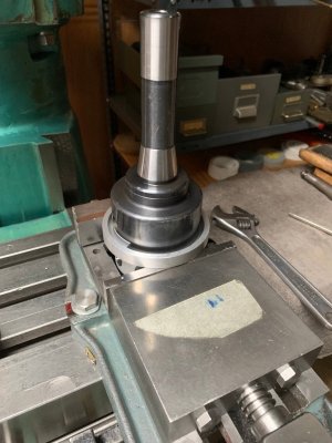
The first item to make was a centering/locating plug turned from soft aluminum to closely fit the bore of the stack and the horizontal ground bore of the boring head (photos 110-111).

This assembly was then set in the horizontal bore of the boring head and left free to rotate as seen in photo 112. The knee of the mill was locked at this point.

The flat base of the locating plug was then set against the angle plate (the vertical slotted face) and when everything was bedded square on the plate, the centre take up cap screw was tightened to both grip the casting and hold the entire assemble firmly against the angle plate. The cross slide of the mill and the quill of the mill's spindle were then tightened. With this procedure one ensures that that boring head is centered on the stack bore and is square to it as one can insert, remove and re-insert the locating plug by just operating the mill table longitudinal feed.

To set the cutter radius, the outer diameter of the smokebox was first measured (5.473") with the cutter radius being set at half (2.737") of this measured value.

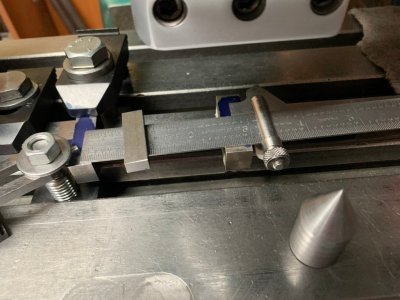
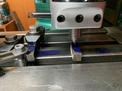
To get as close as possible to this number, the mechanical marking method as seen in photos (115-117) was employed. This involved machining up a new accurate 60 degree center plug to "prick spot" the centre point, setting the slide lower portion of the boring head co incident to the body of the boring head itself (with a larger measuring micrometer) and employing the rube goldberg scratch base plate setup to scribe the fine circular radius line at one end and then the centre point at the other and measuring the distance between the two.

I expected this to be an iterative process taking several adjustments to hit the desired radius exactly but to my great surprise it was right on on with the first try (at least to the finest scale reading of 1/64" with eye loupe magnification and good lighting).

There will likely be a little bit of additional adjustment needed as I will test the advancing machined curve against the OD of the smokebox shell itself as the work proceeds.

to be continued.
 

Attachments

  • 117 Measuring the Resultant Radius.jpeg
    117 Measuring the Resultant Radius.jpeg
    131 KB · Views: 4
  • 116 The Spindle and Boring Head Centre Dot.jpeg
    116 The Spindle and Boring Head Centre Dot.jpeg
    119.9 KB · Views: 4
  • 115 Radius Setting of the Boring Bar.jpeg
    115 Radius Setting of the Boring Bar.jpeg
    125 KB · Views: 4
  • 114 After Clamping.jpeg
    114 After Clamping.jpeg
    129.7 KB · Views: 5
  • 113 Setting the Centered Assembly Square to the Angle Plate.jpeg
    113 Setting the Centered Assembly Square to the Angle Plate.jpeg
    121.9 KB · Views: 3
  • 112 The Locating Plug Stack Casting Fitted to the Boring Head.jpeg
    112 The Locating Plug Stack Casting Fitted to the Boring Head.jpeg
    129.9 KB · Views: 3
  • 111 The Stack Casting Fitted to the Locating Plug.jpeg
    111 The Stack Casting Fitted to the Locating Plug.jpeg
    126 KB · Views: 2
  • 110 The Locating Plug.jpeg
    110 The Locating Plug.jpeg
    125.7 KB · Views: 4
Hi All,

Continuing with the stack machining.

Radiusing the underside of the stack to fit the OD of the smokebox shell with a boring head and boring bar set horizontal in the boring head (photo 118). I used a very slow speed (approx. 60 RPM and a DOC of 0.003" per vertical pass) due to the large radius involved and the interrupted cut which was hard on the HSS boring bar and the setup. I did not want anything to move here under any circumstances so it pays to be cautious. Of course the cutter itself needs to be kept very sharp for this operation.

Photo 119 shows how I checked the stack radius against the OD of the smokebox shell. Only a minute adjustment was needed for the perfect fit.

The final stage was to lap out the boring tool toolmarks using 600 grit wet and dry paper. Not really necessary but I did it (photo 121).

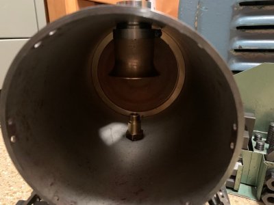
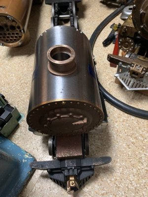
The next operation after fitting the entire assembly together (photos 122-23) will be to "rivet" the stack to the smokebox shell as per prototype practice. However instead of fully riveting it, I am going to thread the rivets into the shell rather than having a true riveted assembly. No one will ever know otherwise.

The setup to do the above will be another interesting one so stay tuned.

to be continued.
 

Attachments

  • 118 Radiusing the Stack Casting Bottom End.jpeg
    118 Radiusing the Stack Casting Bottom End.jpeg
    131.2 KB · Views: 4
  • 119 Checking the Stack Radius Against the Smokebox Shell.jpeg
    119 Checking the Stack Radius Against the Smokebox Shell.jpeg
    142.8 KB · Views: 4
  • 121 Lapping Out the Tool Marks After Radiusing the Stack Bottom End.jpeg
    121 Lapping Out the Tool Marks After Radiusing the Stack Bottom End.jpeg
    158.5 KB · Views: 5
  • 122 The Stack Assembly Installed in the Smokebox.jpg
    122 The Stack Assembly Installed in the Smokebox.jpg
    148.4 KB · Views: 4
  • 123 The Stack Assembly Installed in the Smokebox.jpg
    123 The Stack Assembly Installed in the Smokebox.jpg
    157.7 KB · Views: 8
Nice work. Loco's have a lot of challenging parts & machining ops.
Those cast parts, roughly when would they have been made? Are they still available as kits or getting to be slim pickens like many other model castings?
 
Hi Peter,

All of the stack and petticoat bronze castings which I am using came from Blackgates model engineering in the UK. They are for the Columbia a 3.5" gauge USA Northern (4-8-4) which was described by Martin Evans in the UK model magazine The Model Engineer in the 1980's. All of the castings for this locomotive are still available from Blackgates but they are not cheap. Quite a few Columbia Locomotives have been constructed and are running and several part constructed locomotives are for sale at the moment if you Google Blackgates Columbia.

I ordered 3 sets of these stack castings last year for the Hoffman Hudson Northern which I am finishing as well as for other Hoffman Hudson's which I have. The USA designs for many of there locomotives are quite similar/generic so these castings will look perfectly fine on the model here. With shipping, the cost was nearly $500. Canadian for the three sets of castings.

The Hoffman Hudson Northern is basically a New York Central (NYC) Hudson (4-6-4) stretched to a Northern (4-8-4). THe Hoffman Hudson was a Canadian design produced by Karl Hoffman originally from Kitchener, Ontario and dates back from the late 50's. I wrote about the entire Hoffman Hudson history on the International Brotherhood of Live Steamers (IBLS) website under the title "The Hoffman Hudson Story" so you can find it all there.
 
Hi skippyelwell,

A photo of of my "riveted in" threaded 1/16" dia. soft iron rivets on another 3/4" scale Hoffman Hudson which I have. The rivets are commercial model engineering supplies.

How to put them in and get them out without destroying or marring these tiny rivets; well some tricks have to be learned when building live steam locomotives.

124.jpg
 
Hi All,

Changing direction for the moment as I have to await something to be delivered before I can machine (i.e. final contour and trim) the outside of the stack casting.

I need to install the front deck plate, one which I machined a decade or two ago to fit another Hoffman Hudson.

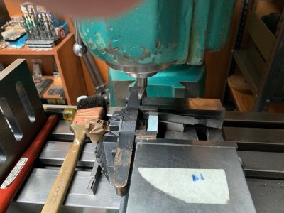
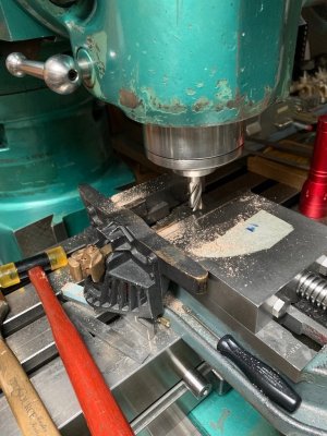
All that has to be done is to machine down the front buffer beam frame lugs to have the top of the deck plate sit flush with the top of the main frames (also known as the front rails) and to install it. This involves some final fitting of the plate. If everything was dead square and parallel here it would be no problem but rarely it is so some final fitting has to be undertaken.

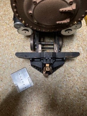
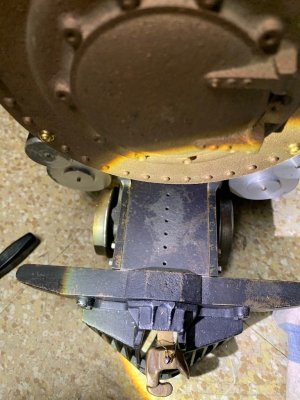
Photos 125 and 126 show the setup used for the machining of the front buffer beam frame lugs. I needed to be careful here not to machine too much material away as it would encroach on the frame attachment bolts. That is why there are the cutouts on the underside of the front deck plate on each side at the front of the plate (photo 127). At these locations the front deck plate is only 1/16" thick.

After some trial fitting the deck plate now sits flush and fits tightly (a tap fit) between the front rails (photo 128).

to be continued.
 

Attachments

  • 125 The Setup to Machine Down the Front Buffer Beam Frame Lugs.jpg
    125 The Setup to Machine Down the Front Buffer Beam Frame Lugs.jpg
    137 KB · Views: 16
  • 126 Machining the Front Buffer Beam Frame Lugs.jpg
    126 Machining the Front Buffer Beam Frame Lugs.jpg
    179.7 KB · Views: 14
  • 127 The Underside of the Front Deck Plate.jpg
    127 The Underside of the Front Deck Plate.jpg
    194.9 KB · Views: 14
  • 128 The Front Deck Plate Installed Between the Front Rails.jpg
    128 The Front Deck Plate Installed Between the Front Rails.jpg
    148.3 KB · Views: 21
Hi All,

Moving on with the stack casting machining as I had previously machined (radiused) the bottom stack flair to conform to the radius of the smokebox shell. However, I was not quite satisfied with the resultant fit between the two parts and I knew I wanted to have and should have a perfect fit here. So I re-set up the stack on the angle plate and remachined the radius.

In retrospect, there is a hard way and easier way to do this and of course I went ahead and did it the hard way again! I will describe the easier way if I ever need to do something like this again but I never describe anything which I have not actually done myself.

So, some "improvements" over the way I did it the first time.

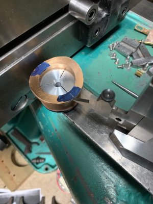
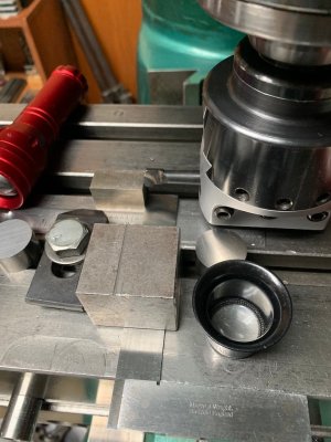
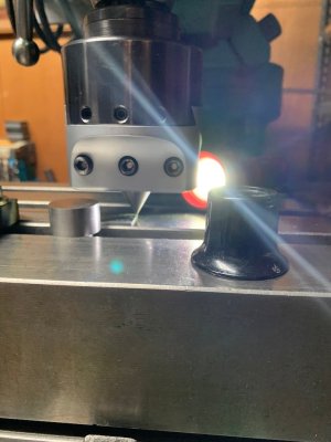
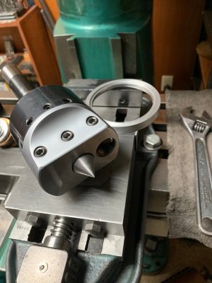
Photo 129 shows the close fitting setting rig which was carefully lathe turned to be a push fit over the body of the boring head. I used the ring to dead align the body and the offset slide of the boring head to bring everything on to dead centre as this gave me an exact "zero" position when setting the cutter radius. The sixty degree turned plug seen in photo 130 fits the centre hole of the slide and is used to pick up the zero position (the exact end) of the 6" engraved rule as seen in photo 131. Good lighting and an eye loupe were used to pick up the end of the rule as seen in the photo. As this operation really needs 4 hands and I only have two, the 6" rule is first set flat to the table of the mill and two dead equal sized tee slot plugs were used to align the rule dead parallel to the tee slot. The rule also needs to be clamped the the table of the mill as it cannot shift or move at all for this operation to work. I do not have any digital aids so this is purely a mechanical setup.

The outside diameter of the smokebox shell was then carefully measured and the setting radius on the boring bar was 1/2 of this measured diameter which turned out to be 2-47/64" exactly (2.734") from the previously picked up "zero" position. The boring bar was placed in the horizontal cross slot of the boring bar slide, very lightly clamped and the tip of the boring bar set to this radius.

How is shown in photo 132. Using a square set from the front edge of the table of the mill (needed 4 hands again) hence the large steel block sitting on the blade of the square to keep it flat, the 2-47/64" graduation on the scale was picked up with good lighting and my trusty eye loupe splitting the graduation line in half. Lots of fiddling here so one needs both patience and determination and check, check, check. The smaller squared steel block seen in photo 132 rests against the outer edge of the blade of the square at exactly the split 2-47/64" graduation and the boring bar was then gently tapped on its end until the tip of the bar just very lightly grazed the end of the smaller block. Everything was then tightened and checked to see that nothing had moved.

Photos 133 and 134 you can ignore as it was used to find the centre of the saddle radius in relation to the stack bore as one has to be aligned (coincident) with the other and not offset one with the other. This has to be determined also as we are creating a partial arc here which is quite different (and much more critical) than using the boring head just to bore a circular hole. It really didn't work very well so in the end I had to rely on the cut and try method. So, as machining proceeded, I would place the smokebox shell against the stack and see how the two parts mated (or didn't) and make adjustments accordingly. I got away with it as the parts did mate perfectly in the end but it was mostly luck. However, there is a better way which I will briefly describe in principle.

This better way needs an extra mill accessory which you may or may not have (I have it). Once can employ a semi universal Brown and Sharpe type dividing head, the body of which will rotate from the horizontal to the vertical all in the same plane which is what is needed. The stack casting would first need to be carefully set in the 3 jaw chuck of this assembly and centered as close as possible to the bore or to the OD of the casting. It is not easy to do this because of its shape but, with care, it can be done. The assembly is first rotated vertical to machine the central bore. However, it is best not to rely on the units graduations alone for this critical alignment. I also have a ground test bar which can be held in a collet in the spindle of the mill to ensure verticality to a very high degree.

After machining (boring ) the central bore to size, the assembly is then rotated to the horizontal position for the machining of the bottom flair (radius) on the casting. This will ensure concentricity of the two curved surfaces. Many times I have unscrewed the chuck and the workpiece from a machines spindle and replaced it later without losing concentricity if your machine's spindle is in good condition. This way one can employ another ground test bar and indicator to ensure dead level without having to rely on the units graduations directly when conditions are critical. The pre setting shown in photos 129-132 still has to be done. This is what I will do in the future but I haven't actually done it to date this way so there may be hidden flaws; so beware, don't take my word as gospel.

Photos 135-137 show the results and I am extremely pleased with what I now see but it really was a very tense time.

to be continued.

 

Attachments

  • 137.jpg
    137.jpg
    141.6 KB · Views: 9
  • 136.jpg
    136.jpg
    162 KB · Views: 8
  • 135.jpg
    135.jpg
    197.3 KB · Views: 7
  • 134 Setting the Scribed Centreline Vertical.jpg
    134 Setting the Scribed Centreline Vertical.jpg
    145.9 KB · Views: 7
  • 133 Locating and Scribing the Centreline of the Stack Bottom Flair.jpg
    133 Locating and Scribing the Centreline of the Stack Bottom Flair.jpg
    138.7 KB · Views: 7
  • 132 Setup to Set the Boring Bar Tip at the Desired Radius.jpg
    132 Setup to Set the Boring Bar Tip at the Desired Radius.jpg
    140.8 KB · Views: 7
  • 131 Zero Setting Point Setup on the 6 Inch Graduated Scale.jpg
    131 Zero Setting Point Setup on the 6 Inch Graduated Scale.jpg
    98.6 KB · Views: 7
  • 130 Sixty Degree  Pointed Plug Set in Boring Head.jpg
    130 Sixty Degree Pointed Plug Set in Boring Head.jpg
    124.2 KB · Views: 7
  • 129 Made Up Setting Ring to Perfectly Align the Body and the Slide of the Boring Head.jpg
    129 Made Up Setting Ring to Perfectly Align the Body and the Slide of the Boring Head.jpg
    130.9 KB · Views: 9
Hi All,

This seems to go on forever and it does.

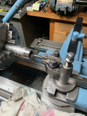
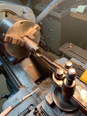
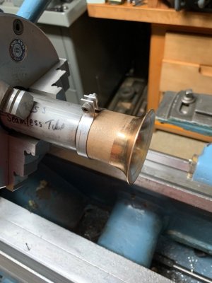
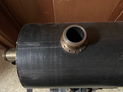
This time I need to add a slight extension to the stainless steel stack liner as, despite all my calculations and checks, the stack liner ended up being 3/16" below the top of the stack instead of flush with the top. The liner needs to be tapered right to the top of the stack to have the full venturi effect and a smooth exit of all the combustion gases.

So back to fighting with the tough 304 stainless which needs to be a tap fit on the OD to the stack bore and have the 3.5 degree internal taper on the ID as well as matching the ID of the existing stack liner at the junction of the two pieces. Just a lot of additional careful turning/boring and time.

As an aside, has anyone worked with 304 stainless? Is there a better carbide grade to use when boring this material rather than the C5 which I am using? The C5 does the job and leaves a good finish, when sharp and new, but it rapidly dulls the cutting edge.

Next up another tense operation to complete.

to be continued.
 

Attachments

  • 139 The Stack Extension Piece Bedded in the Stack Casting Assembly.jpg
    139 The Stack Extension Piece Bedded in the Stack Casting Assembly.jpg
    152.9 KB · Views: 3
  • 138 Grinding the Stack Extension Piece to Finished Thickness.jpg
    138 Grinding the Stack Extension Piece to Finished Thickness.jpg
    158.4 KB · Views: 3
  • 137 Turning the Short Stainless Stack Liner Extension Piece.jpg
    137 Turning the Short Stainless Stack Liner Extension Piece.jpg
    152.3 KB · Views: 3
  • 136 Facing the Stack Casting to Near Final Height.jpg
    136 Facing the Stack Casting to Near Final Height.jpg
    155.7 KB · Views: 3
Hi All,

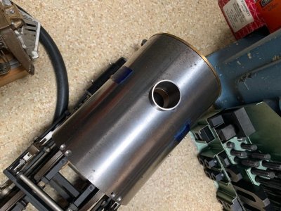
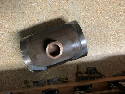
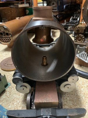
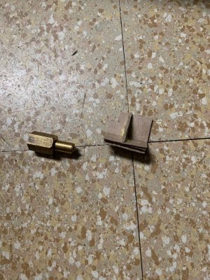
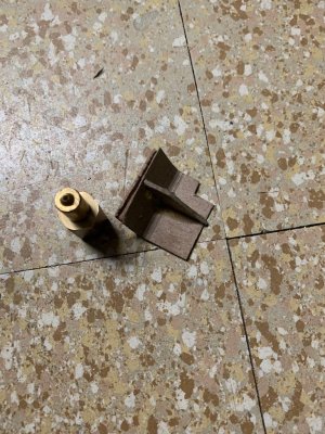
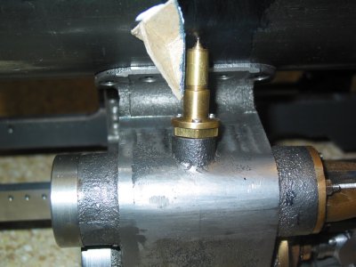
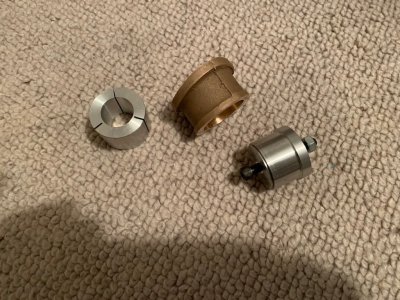
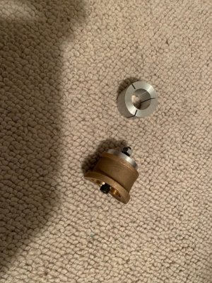
The next operation is to locate and drill the steam downcomer pipe openings in the smokebox shell. You can screw this operation up faster than one can say oh sh..t as they have to be drilled at an oblique angle through and exactly at the right location on the shell.

In order to minimize this happening, I made up the two locating and aligning pieces as seen in photos 140 and 141.

How they are used is seen in photo 58 from another of my locomotive projects. Even with all of this, it still isn't easy.

to be continued.
 

Attachments

  • 140 Steam Downcomer Pipes Locating and Aligning Pieces.jpg
    140 Steam Downcomer Pipes Locating and Aligning Pieces.jpg
    241.4 KB · Views: 6
  • 141 Steam Downcomer Pipes Locating and Aligning Pieces.jpg
    141 Steam Downcomer Pipes Locating and Aligning Pieces.jpg
    222.5 KB · Views: 5
  • 58 Closeup View of Pointed Plug and Inked Cardboard Aligning Piece.JPG
    58 Closeup View of Pointed Plug and Inked Cardboard Aligning Piece.JPG
    538.2 KB · Views: 5
Last edited:
Back
Top